Impact of GIS Disconnector Operations on Secondary Equipment and Mitigation Measures
1.Impacts of GIS Disconnector Operations on Secondary Equipment
1.1 Transient Overvoltage Effects
During opening/closing operations of Gas-Insulated Switchgear (GIS) disconnectors, repeated arc reignition and extinction between contacts cause energy exchange between system inductance and capacitance, generating switching overvoltages with magnitudes 2–4 times the rated phase voltage and durations ranging from tens of microseconds to several milliseconds. When operating short busbars—where disconnector contact speed is slow and no arc-quenching capability exists—pre-strike and re-strike phenomena produce Very Fast Transient Overvoltages (VFTOs).
VFTOs propagate through internal GIS conductors and enclosures. At impedance discontinuities (e.g., bushings, instrument transformers, cable terminations), traveling waves reflect, refract, and superimpose, distorting waveforms and amplifying VFTO peaks. With steep wavefronts and nanosecond-scale rise times, VFTOs induce transient voltage surges at secondary equipment inputs, risking damage to sensitive electronics. This can cause protective relays to maloperate—triggering unwarranted tripping—and disrupt high-precision signal processing and data transmission. Additionally, VFTO-generated high-frequency electromagnetic interference (EMI) degrades communication modules, increasing bit error rates or causing data loss, thereby impairing substation monitoring and control functions.
1.2 Enclosure Potential Rise
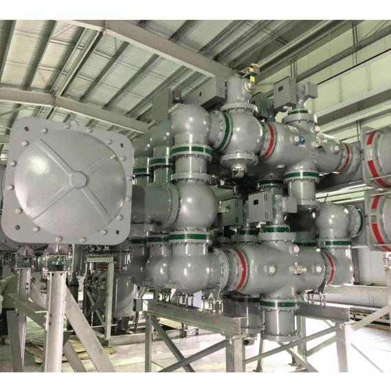
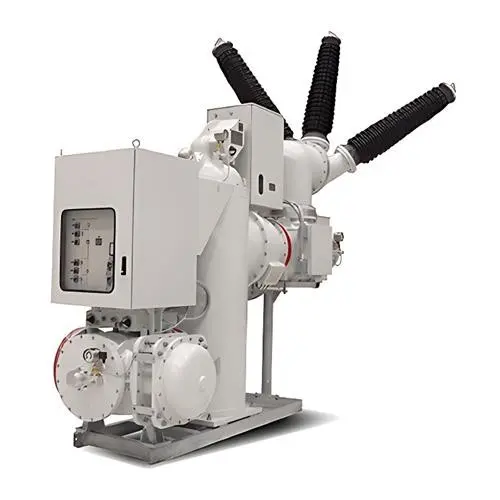
As China expands its ultra-high-voltage (UHV) and extra-high-voltage (EHV) grids, electromagnetic interference from GIS disconnector operations has become increasingly severe. The coaxial structure of GIS—comprising inner aluminum/copper conductors and outer aluminum/steel enclosures—exhibits excellent high-frequency transmission. Due to the skin effect, high-frequency transient currents flow along the outer surface of the conductor and inner surface of the enclosure, typically preventing field leakage and maintaining the enclosure at ground potential under normal conditions.
However, when VFTO-induced transient currents encounter impedance mismatches (e.g., at bushings or cable terminations), partial reflection and refraction occur. Some voltage components couple between the enclosure and earth, causing instantaneous potential rise on the otherwise grounded enclosure. This poses risks to personnel safety and may degrade insulation between the enclosure and internal conductors, accelerating material aging and reducing equipment lifespan. Moreover, this elevated potential propagates via cables and connected devices into secondary systems, inducing EMI that leads to false tripping, data errors, or even internal breakdowns—directly threatening power system reliability.
1.3 Electromagnetic Interference (EMI)
In GIS substations, disconnector/breaker operations and lightning strikes generate transient electromagnetic fields that affect secondary systems via conducted and radiated coupling.
Conducted interference arises through instrument transformers and ground potential differences. VFTOs couple from primary to secondary circuits via stray capacitance and inductance in transformers. They also inject into the grounding grid through grounding electrodes, elevating the entire ground potential and creating ground loops that destabilize secondary equipment.
Radiated interference occurs when transient EM fields propagate through space, directly coupling into secondary cables and devices. Electric field coupling affects high-impedance nodes, causing signal distortion or false triggering—especially sensitive to distance, field orientation, and device geometry. Magnetic field coupling induces electromotive forces in circuit loops per Faraday’s law; its severity depends on field strength, rate of change, and loop area.
1.4 Mechanical Vibration Effects
Disconnector operations induce mechanical vibrations due to contact impact, friction, and electromagnetic forces during make/break actions. Rapid separation during opening or forceful engagement during closing generates shockwaves that vibrate the GIS structure. Transmission through linkages and gears further propagates vibrations to adjacent secondary equipment.
Such vibrations can loosen mechanical fasteners, degrade electrical connections, increase measurement errors, or—under extreme conditions—cause short circuits. Long-term exposure accelerates aging of both mechanical and electronic components, shortening equipment life and compromising reliability.
2.Mitigation Measures for Secondary Equipment Protection
2.1 Optimized GIS Structural Design
Material Selection: Use SF₆ mixtures with higher dielectric strength; select low-loss, high-conductivity materials (e.g., Cu/Al) for shielding; optimize busbar length and capacitance to suppress VFTO amplitude.
Structural Improvements: Smooth conductor and shield geometries to reduce electric field concentration; improve insulator support design for uniform field distribution; implement controlled disconnector operation speeds and add snubber circuits to absorb transient energy.
Vibration Control: Install hydraulic buffers or springs in operating mechanisms; use rubber dampers between GIS and foundations; enhance contact surface precision to minimize impact forces.
2.2 Enhanced Shielding and Grounding
Shielding: Enclose sensitive secondary devices (e.g., relays, communication units) in conductive enclosures (galvanized steel/aluminum) with sealed seams. Use shielded or double-shielded cables with proper termination; apply filtered connectors and mesh screens on vents. For short cables (<10 m), use single-point grounding; for longer runs, adopt multi-point grounding to minimize induced voltages.
Grounding: Maintain grounding resistance ≤4 Ω. In high-resistivity soils, deploy interconnected grounding grids with vertical rods. Use single-point grounding for analog circuits and multi-point grounding for digital/high-frequency systems. Optimize grid layout (e.g., rectangular mesh with cross-junction electrodes) to ensure uniform current dispersion and low potential gradients.
2.3 Filtering and Suppression Technologies
Filters: Install power-line filters at secondary equipment inputs to block high-frequency noise. Apply digital signal filtering algorithms to enhance data integrity in communication channels.
Surge Protection: Deploy ZnO arresters near secondary equipment to clamp VFTOs and switching surges. Use surge protective devices (SPDs) on signal and communication lines to divert transient energy to ground, ensuring stable weak-signal transmission.
2.4 Strengthened Secondary Equipment Hardening
Hardware Protection: Reinforce mounting brackets with thicker steel and added stiffeners. Isolate equipment using rubber mounts or dual-stage vibration isolators. Secure PCBs with thicker substrates, edge fixings, and damping pads. Pot critical components (e.g., ICs, relays) in encapsulants or elastic holders to prevent loosening. Avoid long, thin traces to reduce fracture risk.
Software Protection: Implement checksums and error-correcting codes (ECC) to detect/correct data corruption. Insert “NOP” (no-operation) instructions in firmware to allow recovery from EMI-induced program jumps, preventing deadlocks and enhancing system resilience.
3.Conclusion
A thorough understanding of how GIS disconnector operations impact secondary equipment reveals that comprehensive mitigation strategies are essential for grid reliability. During design, construction, and operation of power systems, electromagnetic compatibility (EMC) between GIS and secondary systems must be prioritized. By integrating structural optimization, robust shielding/grounding, advanced filtering, and hardware/software hardening, the adverse effects of disconnector-induced transients, EMI, and vibration can be effectively minimized—ensuring safer, more reliable, and resilient power delivery.