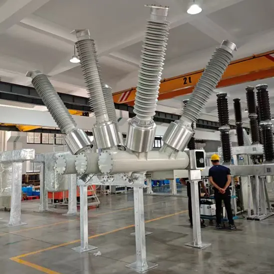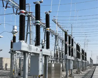
Live Tank SF6 Circuit Breaker
What component is used for SF6 pressure and density monitoring?
How is the monitoring component arranged and what are key field‑reading considerations?
The RHB‑series outdoor live‑tank (post‑type porcelain insulator) SF6 circuit‑breaker adopts a pointer‑type SF6 density relay with analog dial for SF6 pressure‑density monitoring. Complying with IEC requirements for high‑voltage switchgear sealed gas compartments, it continuously monitors equipment operating conditions and detects gas anomalies to ensure reliable insulation and arc‑extinguishing performance.
The density relay is installed inside the circuit‑breaker base. Fabricated from bent steel plates and fitted with cover plates, the base achieves IP2X degree of protection. Inside the base are three‑phase interconnected SF6 gas‑filling pipelines and the density relay. The pressure gauge dial and nameplate are fitted on the front for convenient on‑site visual inspection. Three installation access holes are located on the rear, and the control cabinet is rigidly fastened to the base with six M16 bolts.
Important notes extracted from the product manual:
- When the pole‑column gas‑filling valve is disconnected from the gas‑filling pipeline, the pipeline forms an independent sealed chamber. The reading shown represents pressure inside the pipeline only, not the pressure within pole‑column gas compartments.
- A three‑way joint is installed below the pressure gauge; its spare port acts as the gas‑filling connection for the circuit‑breaker.
- All dial readings indicate absolute pressure values referenced to 20 °C, in compliance with IEC marking requirements for SF6 gas compartments.
What core functions does the pointer‑type SF6 density relay provide?
What role does temperature compensation play, and how can we distinguish temperature‑caused fluctuations from actual gas leakage?
Unlike ordinary pressure gauges, this density relay features temperature compensation, condition monitoring and dual‑level signal output, satisfying IEC 62271‑series design requirements for SF6‑filled sealed compartments.
- Real‑time pressure‑density monitoring It continuously measures SF6 gas density (pressure converted to the 20 °C reference condition) within the three‑phase interconnected gas compartments. Field operators can directly read gas‑condition status from the dial to identify potential faults at an early stage.
- Built‑in temperature compensation (core feature) SF6 pressure changes with ambient temperature; however, temperature variation does not alter actual gas density or impair insulation and arc‑extinguishing performance.
Operating logic of the temperature‑compensated density relay: ‑ Contact contacts remain inactive if pressure deviation originates purely from ambient‑temperature changes, filtering out “false pressure variations” caused by temperature drift. ‑ Signal outputs are triggered only when real density drop occurs due to SF6 gas leakage.
This mechanism prevents false alarms and false interlocks induced by temperature changes — this is the essential difference between a density relay and an ordinary pressure gauge.
What protective functions do alarm and interlock signals perform respectively?
As SF6 density gradually drops due to leakage, the relay sends two groups of switch‑output signals to the secondary control circuit in sequence: ‑ Alarm signal: Activated when density reaches the alarm threshold, alerting maintenance personnel to conduct leak checks and SF6 gas top‑ups. ‑ Interlock signal: Activated before density falls below the minimum functional pressure. It blocks the circuit‑breaker closing and tripping control loops.
IEC standard requirement: Circuit‑breakers shall be prevented from opening or closing operations when SF6 density drops below minimum functional pressure. This avoids breaking failures, equipment damage and further accident escalation under low‑SF6‑pressure conditions.
What are the threshold parameters for SF6 pressure monitoring of RHB‑series products?
How are pressure setpoints applied in the density‑relay protection logic?
Note: Alarm setpoints lie between the rated filling pressure and minimum functional pressure. Minimum functional pressure is the lower‑limit pressure guaranteeing the breaker’s insulation and breaking performance. The annual SF6 leakage rate is less than 0.5 %, with a 30‑year maintenance interval, meeting IEC leakage requirements for sealed gas compartments.
| Model |
Rated Filling Pressure (MPa abs @20 °C) |
Minimum Functional Pressure (MPa abs @20 °C) |
| RHB‑52 |
0.5 |
0.4 |
| RHB‑72.5 |
0.6 |
0.5 |
| RHB‑123 / RHB‑145 |
0.6 |
0.5 |
| RHB‑170 / RHB‑252 / RHB‑362 / RHB‑420 / RHB‑550 |
0.6 |
0.5 |
The density relay executes monitoring and protection based on the operating range bounded by rated filling pressure and minimum functional pressure. Alarm and interlock contact setpoints are factory‑calibrated against this pressure window.
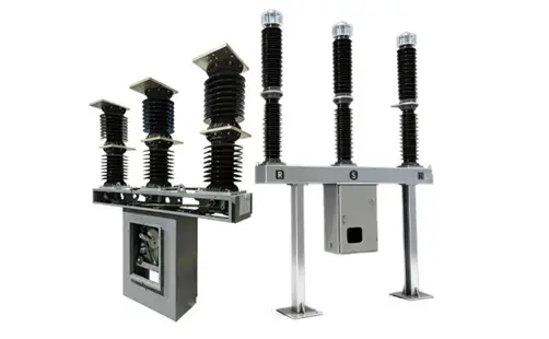
Live Tank SF6 Circuit Breaker 40.5kV to 550kV
What overall safety benefits does SF6 pressure‑and‑density monitoring deliver?
What are the key take‑aways regarding SF6 density monitoring?
- Monitoring hardware and layout: A pointer‑type SF6 density relay with dial is mounted inside the breaker base and connected to three‑phase SF6 gas‑filling pipelines. All dial readings are absolute‑pressure values converted to the 20 °C reference condition.
- Core capabilities: Real‑time SF6 density measurement; temperature‑compensated design responding solely to density loss from gas leakage (ignoring temperature‑driven pressure swings); dual‑stage alarm and interlock signal outputs.
- Safety benefits: Designed in accordance with IEC 62271‑1 and IEC 62271‑100 standards. It avoids false alarms caused by ambient‑temperature variation, provides early warning and operational interlock upon SF6 leakage, maintains insulation and interrupting capability, and mitigates severe operation risks under insufficient SF6 pressure.
Practical tip: On‑site verification and setpoint checking of the density relay shall follow the official product manual, be performed under power‑off conditions, and only after adequate safety measures are put in place.
Edited From:Dyson

 Login