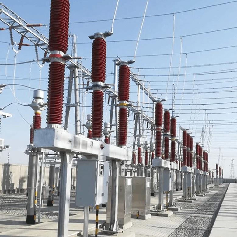
High - voltage SF₆ circuit breakers are three - phase AC 50Hz outdoor high - voltage electrical equipment. They adopt a self - energy arc - extinguishing chamber structure and are equipped with spring operating mechanisms. These circuit breakers feature a simple structure, convenient operation, and high safety and reliability. Therefore, they are widely used for the control and protection of transmission and distribution lines and can also serve as tie - type circuit breakers.
The 110kV system of a certain substation employs this type of circuit breaker. However, as the years of operation increase, the imperfections in the secondary circuit gradually come to light. In particular, faults where the closing coil is burned out due to issues in the energy - storage circuit occur frequently. This article takes a special fault that occurred during the operation of this type of circuit breaker as an example to conduct an analysis and propose corresponding improvement measures.
1 Fault Phenomenon
The 110kV SF₆ circuit breaker in a 220kV substation uses a spring operating mechanism as the energy - storage device. When the circuit breaker is in the open state and the closing electrical circuit indicates normal, the operating personnel send a closing operation signal. However, the circuit breaker not only fails to close but also has its closing coil burned out. Why does this special fault occur when all the closing conditions are met? To prevent the recurrence of similar faults, a serious research and analysis must be carried out.
2 Fault Analysis
In the closing control circuit of this type of circuit breaker, YF is the "local/remote" transfer switch (as shown in Figure 1). When remote closing is required, the positive pole of the operating power supply goes through C7→YF contacts 3 - 4→the normally closed contacts 31 - 32 of the anti - tripping auxiliary relay 52Y→the normally closed contacts 21 - 22 of the spring energy - storage relay 99CN→the normally closed contacts 31 - 32 of the relay 49MX→the normally closed contacts 31 - 32 of the closing spring status monitoring relay 33HBX→the normally closed auxiliary contacts 1 - 2 and 5 - 6 of the circuit breaker→the closing coil 52C→the normally closed contacts 31 - 32 of the SF₆ gas low - voltage locking relay 63GLX→the negative pole of the operating control power supply. When the power supply voltage is applied to the closing coil 52C, the electromagnet acts to close the circuit breaker.
Based on the above circuit analysis, for the closing coil 52C to be energized, the following four conditions must be met:
The coils of 52Y, 49MX, and 33HBX are not energized, and their normally closed contacts 31 - 32 are connected in the closing control circuit;
The coil of 99CN is not energized, and its normally closed contacts 21 - 22 are connected to the closing control circuit;
52B is in the open position, and its normally closed auxiliary contacts 1 - 2 and 5 - 6 are connected to the closing control circuit;
The normally closed contacts 31 - 32 of the SF₆ gas relay 63GLX are closed, connecting the closing control circuit.
Through analysis, it can be seen that when all the above conditions are met, the control voltage can be applied to the coil, resulting in the burnout of the closing coil. When the chassis is initially inspected, it is found that the SF₆ gas pressure gauge indicates normal, while the mechanical indication of the closing spring shows no energy storage. Why can the closing circuit be conducted when there is no energy storage? Therefore, further inspection of the closing spring energy - storage circuit is required.
As can be seen from the motor energy - storage circuit in Figure 1, when the closing spring of this circuit breaker is not energized, the normally closed contact C - NC of the energy - storage limit switch 33HB installed on the back of the circuit breaker mechanism controls the 99CN and 33HBX relays simultaneously, connecting the positive pole of the DC control power supply:
The spring energy - storage relay 99CN is energized and operates, and its power supply connects the motor circuit, and the closing spring is electrically energized for energy storage; at the same time, the normally closed contacts 21 - 22 of 99CN are disconnected in the closing control circuit, avoiding the circuit breaker from accidentally closing during the spring energy - storage process.
When the coil of the closing spring status monitoring auxiliary relay 33HBX is energized, the normally closed contacts 31 - 32 of 33HBX connected in the closing control circuit are disconnected. This ensures that during the spring energy - storage process, the secondary closing circuit of the circuit breaker is in the open position, having a reliable dual - locking function with the normally closed contacts 21 - 22 of 99CN.
When the spring energy storage is in place, the mechanical components of the energy - storage mechanism disconnect the normally closed contact C - NC of the energy - storage limit switch 33HB. The coils of 99CN and 33HBX lose power, and the energy storage ends. The normally closed contacts 21 - 22 of 99CN and the normally closed contacts 31 - 32 of 33HBX connect the closing control circuit. From the function of the contacts in the component wiring diagram, only when the 99CN and 33HBX relays are in the energized and activated state can the closing circuit be locked. Therefore, based on the above analysis, it is judged that the failure of the normally closed contact C - NC of the energy - storage limit switch 33HB may be the cause of the motor's inability to store energy.

Maintenance personnel opened the rear cover plate of the circuit breaker mechanism on - site and removed the energy - storage limit switch. After inspection and measurement, it was found that the internal contacts of the energy - storage limit switch 33HB were damaged during the energy - storage process, preventing the power supply from passing through its normally closed contact C - NC. As a result, the coils of 99CN and 33HBX could not receive power. The 99CN contactor did not operate, and the power supply could not be connected to the energy - storage motor. Meanwhile, the normally closed contacts 21 - 22 of 99CN and the normally closed contacts 31 - 32 of 33HBX were connected to the closing circuit for a long time. Since the spring mechanism of the circuit breaker was not energized and the secondary closing circuit was conducting, not only could the circuit breaker not close normally, but the closing coil would also be burned out.
3 Treatment and Modification
Simply replacing the energy - storage limit switch cannot essentially solve the special fault described in this article. Due to the unreasonable design and imperfect interlocking mechanism, once the energy - storage limit switch is damaged, it will lead to a failure in the closing circuit. Therefore, the following modifications are made to the energy - storage and closing control circuits:
(1) The energy - storage limit switch 33HB consists of a pair of normally closed contacts and a pair of normally open contacts, with the two pairs of contacts mechanically interlocked. According to the characteristics of the travel switch, the following modifications are made: Connect the normally closed contact C - NC of 33HB to the coil of 99CN, as shown in Figure 2. This modification retains the function of the circuit breaker's closing circuit being disconnected and unable to close during the energy - storage process. Connect the normally open contact O - NO of 33HB to the coil of 33HBX. After the spring energy storage is in place, the normally open contact O - NO of 33HB closes to connect the coil of 33HBX. At the same time, remove the normally closed contacts 31 - 32 of the relay 33HBX connected in the closing control circuit and replace them with the normally open contacts 43 - 44 of 33HBX. The above modification changes from one pair of contacts controlling two relays to each pair of contacts controlling one relay. This ensures that the closing control circuit cannot be conducted during the non - energy - storage and energy - storage processes. Only after the spring energy storage is in place, when the coil of 33HBX is energized and the normally open contacts 43 - 44 close, can the closing control circuit be connected. At the same time, it also reduces the long - term load on the energy - storage limit switch and extends its service life.
(2) Add a time relay T. Connect the normally closed contacts 31 - 32 of the relay 33HBX in series with the coil of the time relay, and set the operating time limit of the time relay to 15s, which is slightly longer than the spring energy - storage time of the circuit breaker. Adding the time relay can achieve the following: During the 15s when the spring is not energized and during the energy - storage process, the coil of 33HBX is not energized, the normally closed contacts 31 - 32 are closed, and the time relay sends a signal indicating no energy storage. After the spring energy storage is in place, 33HBX is energized and operates, the normally closed contacts 31 - 32 are disconnected, and the time relay stops sending the no - energy - storage signal, indicating that the energy storage is successful.

4 Conclusion
This article focuses on modifying the defects in the control circuit of a 110kV SF₆ circuit breaker. The normally open contact of the energy - storage limit switch is connected in series to the motor control circuit of 99CN, and the normally closed contact of the 33HBX relay connected in series in the closing control circuit is replaced with a normally open contact. This ensures that only when the mechanical components press the energy - storage limit switch 33HB, that is, after the spring energy storage is in place and the 33HBX relay operates, can the closing control circuit be connected.
Meanwhile, the addition of a time relay provides an alarm function for the energy - storage signal. The modified closing control circuit of the circuit breaker not only has a simple and reliable wiring but also helps operating personnel quickly determine whether energy storage has occurred, effectively preventing the failure of the coil burnout caused by lack of energy storage. After the modification and commissioning, all indicators of the secondary circuit of this type of circuit breaker operate normally, parameter tests are correct, and no abnormal faults occur during opening and closing operations.