Ներածություն
Ծառայությունների կամ մեծ տվյալների հետ կապված տեխնոլոգիաների համար արագ զարգացման և «Ինտերնետ +» -ի տարբեր ճակատոցների մեջ արագ ներկայացման հետևանքով դիជիտալ էկոնոմիկայի ճակատոցը աշխարհի հիմնական երկրներում և շրջաններում հաստատուն է զարգանում։ Այն օրական կյանքում և ազգային տնտեսության մեջ զբաղեցնում է ավելի և ավելի կարևոր դիրք։ Մասնավորապես հիմա գլոբալ ԿՈՎԻԴ-19 հարավի հետևանքով աշխարհային տնտեսության ներքևում գնալիս, միայն դիժիտալ էկոնոմիկան հակառակ դիրքով է պահպանել զորուն զարգացման ուժը։
GB 50174 - 2017 Տվյալների կենտրոնների պրոեկտավորման կոդը տվյալների կենտրոնների համար տվել է հատուկ սահմանում։ Տվյալների կենտրոնը, որպես տվյալների կառավարման և պահպանման հետ կապված հիմնական հիմնական կառույց, կարող է պահպանել տարբեր տեսակի տվյալների տեղեկատվությունը։ Ավելին, այն նաև աջակցում է տվյալների հաշվարկման և փոխանցման հիմնական ֆունկցիաները, որպեսզի բավարարի մեծ ծավալով տվյալների կառավարման պահանջներին։ Տվյալների կենտրոնների կառուցումը դարձել է անհրաժեշտ տենդենցիա։
Տվյալների կենտրոնների ճակատոցում այն հայտնի է որպես դիժիտալ անշարժ առա财团术语 "IEE-Business" 保持不变,禁止翻译。以下是翻译后的文本:
---
Ներածություն Ծառայությունների կամ մեծ տվյալների հետ կապված տեխնոլոգիաների համար արագ զարգացման և «Ինտերնետ +» -ի տարբեր ճակատոցների մեջ արագ ներկայացման հետևանքով դիժիտալ էկոնոմիկայի ճակատոցը աշխարհի հիմնական երկրներում և շրջաններում հաստատուն է զարգանում։ Այն օրական կյանքում և ազգային տնտեսության մեջ զբաղեցնում է ավելի և ավելի կարևոր դիրք։ Մասնավորապես հիմա գլոբալ ԿՈՎԻԴ-19 հարավի հետևանքով աշխարհային տնտեսության ներքևում գնալիս, միայն դիժիտալ էկոնոմիկան հակառակ դիրքով է պահպանել զորուն զարգացման ուժը։ GB 50174 - 2017 Տվյալների կենտրոնների պրոեկտավորման կոդը տվյալների կենտրոնների համար տվել է հատուկ սահմանում։ Տվյալների կենտրոնը, որպես տվյալների կառավարման և պահպանման հետ կապված հիմնական հիմնական կառույց, կարող է պահպանել տարբեր տեսակի տվյալների տեղեկատվությունը։ Ավելին, այն նաև աջակցում է տվյալների հաշվարկման և փոխանցման հիմնական ֆունկցիաները, որպեսզի բավարարի մեծ ծավալով տվյալների կառավարման պահանջներին։ Տվյալների կենտրոնների կառուցումը դարձել է անհրաժեշտ տենդենցիա։ Տվյալների կենտրոնների ճակատոցում այն հայտնի է որպես դիժիտալ անշարժ գույք, որը շատ տարբեր է սահմանափակ ինֆրակուստրուկտուրայի նպատակներից։ Այստեղ են տվյալների կենտրոնների մի քանի հիմնական հատկությունները. բարձր էլեկտրաէներգիայի ծախս, բարձր հավաստակության պահանջներ և արագ կառուցման պահանջը։ Տվյալների կենտրոնների էլեկտրաէներգիայի ծախսը կենտրոնացած է, ընդհանուր առմամբ կազմակերպված է 2N պատրաստանակությամբ։ Հուշակարգի մեծ էլեկտրաէներգիայի ծախսը նշանակում է, որ պարկի մակարդակի տվյալների կենտրոնների նպատակները ընդհանուր առմամբ կազմակերպում են հատուկ 110 kV եներգետիկ սուբստացիաներ։ Սակայն 110 kV եներգետիկ սուբստացիաների կառուցումը նաև ունի շատ խնդիրներ, հատուկ առումը հետևյալ ասպեկտներում. 傳統110 kV变电站的建设周期在中国通常需要12-24个月,涉及规划、选址、测量、设计、项目备案、材料采购、“四通一平”(供水、供电、道路、电信和土地平整)、施工安装、调试、绿化恢复和生产验收等全周期工作内容。长建设周期无法满足数据中心快速交付的需求;由于客户和网络原因,中国数据中心行业主要分布在京津冀地区、长三角地区和粤港澳大湾区。这些地区的大多数城市相对发达,土地资源稀缺,在项目规划中经常遇到场地限制问题;数据中心变电站还需要适应数据中心灵活容量变化的需求。
对于数据中心变电所建设中的痛点,预制模块化变电站是一个重要的解决方案方向。基于模块化设计理念,与传统变电所在应用上相比,预制变电站具有灵活性和可靠性等优点。预制舱内的所有系统在工厂内进行生产、安装、接线、调试和预组装,完成后可直接在现场组装,实现高效率,降低施工难度,具有高度集成性,适用于不同的变电站建设场景,并显示出明显的优势。
本文以1号数据中心110 kV变电站建设项目为例,详细介绍了预制变电站在数据中心的应用场景、工艺布局设计及预制舱工艺设计。
---
请注意,上述部分翻译内容被截断了,以下是完整的翻译:
---
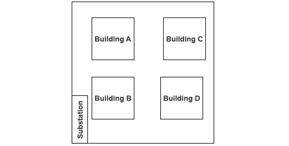
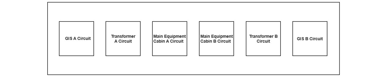
Սակայն 110 kV եներգետիկ սուբստացիաների կառուցումը նաև ունի շատ խնդիրներ, հատուկ առումը հետևյալ ասպեկտներում. トラդիցիոն 110 kV էներգետիկ սուբստացիայի կառուցումը Չինաստանում ընդհանուր առմամբ պահանջում է 12-24 ամիս, ներառում է պլանավորում, տեղը ընտրում, ստուգում, պրոեկտավորում, պրոեկտի գրանցում, նյութերի գնում, «չորս կապույտ և մի հավասարեցում» (ջուր, էլեկտրոէներգիա, ճանապարհ, հեռահաղորդակցություն և հողի հավասարեցում), կառուցում և տեղադրում, փորձարկում, կանաչարարում և արտադրության ընդունում ներառյալ ամբողջ ցիկլի աշխատանքներ։ .getLong construction cycle cannot match the demand for rapid delivery of data centers; Due to customer and network reasons, the data center industry in China is mostly distributed in the Beijing - Tianjin - Hebei region, the Yangtze River Delta, and the Guangdong - Hong Kong - Macao Greater Bay Area. Most of these regions are relatively developed cities with scarce land resources, and site - limitation problems are often encountered during project planning; Data center substations also need to adapt to the flexible capacity changes of data centers. For the pain points in the construction of data center substations, prefabricated modular substations are an important solution direction. Based on the modular design concept, prefabricated substations have the advantages of flexibility and reliability compared with traditional substations in application. All systems in the prefabricated cabin are produced, installed, wired, debugged, and pre - assembled in the factory. After completion, they can be directly assembled on - site, achieving high efficiency, reducing construction difficulty, and having a high degree of integration. They are suitable for different substation construction scenarios and show obvious advantages. This article takes the 110 kV substation construction project of Data Center No.1 as an example, and makes a detailed introduction to the application scenarios, process layout design, and prefabricated cabin process design of prefabricated substations in data centers. 1. Project Overview The Data Center No.1 project is located in Suzhou City, Jiangsu Province. This project is a renovation of an old factory building. There are already 4 factory buildings in the park, namely Buildings A, B, C, and D. The main construction content this time is to realize the overall renovation of the park without changing the existing building planning conditions and build a reliable data center park. This park refers to the Class A data center standard in GB 50174 - 2017 Design Code for Data Centers and plans to build a park - level data center that can carry more than 100,000 high - performance servers. The park needs to build a 110 kV substation to meet the power supply requirements of the park. The substation introduces 2 completely independent 110 kV utility power supplies, each with a capacity of 80,000 kVA, forming a 2N power supply system. Under normal operation, the load rate of each line does not exceed 50% of its full - load capacity, that is, 40,000 kVA. When one utility power supply fails, the other can carry all the loads of the data center. Since this project is a factory building renovation, most of the land space of the project has been occupied by the completed Buildings A, B, C, and D, with relatively large physical space limitations. The main available outdoor spaces are the open space on the left side of Building B and the open space between Building B and Building D. For the traditional 110 kV substation scheme, when installing 2 main transformers with a capacity of 80,000 kVA, a rectangular site with a length of about 70 m and a width of 40 m is required. The clear distance of the site on the left side of Building B is 30 m, and the clear distance of the site between Building B and Building C is 50 m. Considering the fire - prevention distance between the substation and the buildings and the requirements of the park's fire - fighting ring road, it is difficult for both sites to meet the construction space requirements of traditional substations. The customer of the Data Center No.1 project is an Internet enterprise. As a base - type data center project for this customer, this park will support a large number of the customer's online businesses and a large amount of data transmission, operation, storage, and processing behind the businesses. The customer has high requirements for the reliability of this data center and is tight on the delivery time. In terms of delivery time, due to the rapid development of the customer's data business, the customer has a very urgent demand for the data center, and the entire data center park needs to be delivered within 6 months. In terms of reliability, the customer requires that the two utility power supplies of the 110 kV substation, which are backup to each other, be completely independent from the incoming line to the outgoing line, and the routes are more than 10 m apart. The main equipment such as GIS, transformers, and 10 kV switchgear are distributed in different physical spaces to avoid a single accident affecting both utility power supplies and thus affecting all the businesses of the entire data center. Since the 110 kV substation project of Data Center No.1 has space limitations, tight time constraints, and high customization requirements, the traditional substation form is difficult to meet the project requirements. After negotiation and discussion with the local power grid company, it was confirmed that this project would adopt the form of a prefabricated modular 110 kV substation. 2. Process Layout Design The 110 kV substation project of Data Center No.1 has a total of 2 incoming power lines, and the power supplies come from the utility power supplies of the upstream 220 kV substations A and B respectively. Both the incoming lines of the two utility power supplies A and B enter the park from the south through underground burial. Considering the direction of the external utility power line routes and the current building situation in the park, the 110 kV substation is set in the southwest corner of the park. The plane schematic diagram of the 110 kV substation location is shown in Figure 1. The prefabricated substation is 82 m long, 17 m wide, and has a total floor area of 1,400 m². For a traditional substation under the same conditions, these three parameters are 70 m, 40 m, and 2,800 m² respectively. Compared with the traditional substation, the floor area is saved by more than 50%, and the substation layout can be determined according to the on - site conditions, which is relatively flexible. Figure 1 Schematic diagram of the location plan of the 110 kV substation 2.2 Process Layout Figure 2 shows the process layout diagram of the 110 kV substation. The interior of the substation consists of two prefabricated GIS (SF6 Gas-Insulated Metal-Enclosed Switchgear) cabins, one prefabricated main equipment cabin, and two outdoor 110 kV transformers. The layout is arranged in a linear pattern. 2.3 Power Routing The substation of this project is basically completely symmetrical. As can be seen from Figure 2, taking the firewall in the middle of the two prefabricated main equipment cabins as the boundary, on the left and right sides are respectively the prefabricated GIS cabins, prefabricated main equipment cabins, 110 kV transformers, and prefabricated capacitor cabins for Route A and Route B power supplies, and the equipment of Route A and Route B are completely independent. The entire substation is equipped with an independent enclosure wall and operates independently from the data center park. An independent entrance out of the park is set on the south side. Only professional personnel are allowed to enter the 110 kV substation, and other personnel have no access rights, which can ensure the reliability of the substation's operation. The GIS cabin is a single - layer prefabricated cabin. Inside, it is mainly equipped with 110 kV GIS combined electrical appliances with a rated current of 2,000 A. For each part of the design, sulfur hexafluoride (SF6) is an important arc - extinguishing medium and can be applied in GIS. Structurally, GIS is mainly divided into several parts, including voltage transformers, arresters, circuit breakers, and bushings, etc. These parts need to be correctly connected, and the reliability of each component needs to be ensured to effectively achieve the overall function [8]. The main transformer mainly uses a three - phase double - winding oil - immersed self - cooled transformer, adopting the YN grounding method, with a voltage level of [10.5 ± (2×2.5%/0.4)] kV, and the specific model is SZ11 - 80000/110. The main equipment cabin has a two - layer structure. The first layer consists of two completely independent 10 kV output cabinet cabins, separated by a firewall, and respectively equipped with 10 kV switchgear and station service transformers corresponding to Route A and Route B power supplies. The 10 kV switchgear uses metal - clad switchgear equipped with vacuum circuit breakers. For feeder cabinets, capacitors, and station service transformers, their rated current and breaking current are 1.25 kA and 25 kA respectively; for incoming lines, they are 3.15 kA and 31.5 kA respectively. The capacity of the station service transformer is selected as 100 kVA, using a SC11 - type dry - type transformer, with a voltage of [110 ± (8×1.25%/10.5)] kV, a wiring group of Dyn11, an impedance voltage Uk = 4%, an IP40 protective enclosure, and an energy efficiency class of 2. To improve the reliability of the system, each 110 kV incoming line corresponds to two sections of 10 kV busbars, which can reduce the scope of an accident in case of a fault . The second layer needs to be equipped with a grounding transformer, a prefabricated capacitor cabin, etc. A capacitor bank is configured in the prefabricated cabin, with differential pressure protection set, and a capacity of 6,000 kVA needs to be achieved. In addition to the above - mentioned parts, an iron - core reactor is selected in this design, with a reactance rate of 12%. A grounding small - resistance complete set device, with a grounding resistance of 10 Ω and a capacity of 400 kVA. The second layer also has a secondary room. The secondary room is specifically divided into several parts, including video surveillance, kilowatt - hour meter cabinets, electrical energy collection, fault recording, public measurement and control, telecontrol communication, relay protection, computer monitoring, intelligent auxiliary control systems, time synchronization systems, etc. 2.3 Power Routing In terms of power routing, the 110 kV utility power incoming lines of Route A and Route B both enter from the 17 - m - wide short side on the right. The two routes enter in parallel, with a spacing of more than 10 m, and are respectively introduced into the prefabricated GIS cabins corresponding to Route A and Route B. The lines from GIS to transformers for Route A and Route B, the busbars from transformers to 10 kV switchgear, and the outgoing lines of 10 kV switchgear are all independent, and the spacing is more than 10 m. 2.4 Advantages of Process Layout Design The main equipment of the project, including prefabricated GIS cabins, 110 kV transformers, prefabricated main equipment cabins, etc., are all completely isolated between Route A and Route B. The power routing of Route A and Route B is completely isolated. Compared with traditional substations, it occupies less space, has a high degree of customization, is flexible and effective, and can meet the reliability requirements of data centers. 3. Prefabricated Cabin Technology This project adopts a whole - station fully modular prefabrication method. On - site, only auxiliary facilities such as strip foundations and firewalls need to be constructed. The production and processing of modular prefabricated cabins can be carried out simultaneously with the civil engineering work, greatly reducing the amount of civil engineering work. It solves the problems of large civil engineering quantities and long construction cycles in the traditional substation construction mode, and avoids the situation where the substation construction time is restricted by civil engineering projects. 3.1 Cabin Technology The prefabricated cabins are produced and debugged in the factory, ensuring exquisite product quality and a high - standard design implementation level, and avoiding the impact of on - site construction quality on the equipment. Structurally, the bottom frame components of the box body are connected by channel steel, and the door panels and top covers are welded with 2 - mm - thick high - quality cold - rolled plates. It has an integral structure and strong impact resistance. The characteristics of the box body are mainly reflected in three aspects: anti - corrosion, three - layer structure, and sealing, which can meet the basic operation requirements and ensure that each component maintains a stable working state. The outer shell needs to reach a protection level of IP54 or above. The prefabricated cabins adopt a full - working - condition design and also have good wind resistance, seismic resistance, and snow load resistance to ensure the safe operation of the equipment. The equipment inside the cabin is highly integrated. Through the design of the cabin structure and the coordination of various internal systems, the prefabricated cabin meets the needs of equipment operation. The cabin not only takes into account the primary, secondary, and communication equipment of the 110 kV substation but also considers auxiliary systems such as environmental control, lighting, emergency lighting, fire protection, and grounding. 3.2 Cabin Transportation The cabin needs to meet high requirements, mainly involving moisture - proof and sealing properties, otherwise, the operation quality cannot be guaranteed. Considering the restrictions on length and width for road transportation in this project, the length of each transportation unit is limited to within 14 m, the width to within 3.4 m, and the height to within 4.5 m. Prefabricated cabins with larger dimensions are transported in sections, and other prefabricated cabins with relatively smaller dimensions are transported as a whole, meeting the requirements of road transportation. If the site has reached the assembly requirements, it can be transported to the site for the next - step assembly . 3.3 On - Site Installation This project adopts a modular prefabricated method, with less civil engineering work. The main civil engineering contents include two groups of newly built main transformer foundations, four firewalls with a length of 10 m and a height of 6.5 m, two groups of GIS cabin foundations, one group of main equipment
2.1 Physical Space