
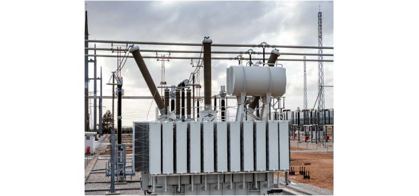
1. Indicators Related to the Utilization Rate of Power Transmission Transformers
The utilization rate of power transmission transformers needs to consider both the cost of transmitting and distributing electrical energy and the utilization efficiency of the equipment itself. The core indicators mainly include three dimensions: load rate, load factor, and equipment life rate.
1.1 Load Rate
It refers to the ratio of the actual load at the moment of maximum load to the rated capacity of the transformer. It can not only reflect the load - bearing capacity of the equipment under different working conditions but also reflect the operational safety of the equipment. In practical applications, the higher the load rate, the higher the effective utilization rate of the transformer. Its value is jointly determined by the safety criteria and the development margin, and the two are independent of each other: within the framework of safety criteria, the more connection objects the line has, the stronger the load - carrying capacity of the system.
1.2 Load Factor
It is the ratio of the average load to the maximum load within a specific time range. It can reflect the load fluctuation characteristics within that time period to a certain extent and also reflect the overall utilization level of electrical equipment. Generally speaking, the higher the load factor, the higher the comprehensive utilization rate of power transmission and distribution equipment.
1.3 Life Rate
It is the ratio of the actual service life of the equipment to the designed standard service life. The standard service life of the equipment is clearly marked in the instruction manual when it leaves the factory. However, during actual operation, the actual life will differ from the standard value due to factors such as the operating environment, load intensity, and load stability. If the life rate is greater than 1, it means that the equipment has played a role beyond expectations, which can indirectly improve the utilization rate and reduce the power transmission cost.
2. Methods to Improve the Utilization Rate of Power Transmission Transformers
2.1 Improve the Load Factor
Balance the load fluctuation through the following measures to improve the equipment utilization efficiency:
2.1.1 Reduce the Peak - Valley Difference
There are obvious daily peak - valley characteristics in industrial and residential electricity consumption: the peak of residential electricity consumption is concentrated between 18:00 and 21:00, and the valley is in the early morning; for industrial electricity consumption, the peak is during the day and the valley is at night. Narrowing the gap in electricity consumption between peak and valley periods can stabilize the load curve, thereby increasing the load factor and the utilization rate of the transformer.
Specifically, a time - of - use electricity price mechanism can be adopted: increase the price for electricity consumption during peak periods and reduce the price during valley periods, and achieve "peak shaving and valley filling" through market regulation. This measure can not only improve the utilization rate of equipment but also enhance the stability of the power transmission and distribution system. At present, some regions in China have not implemented time - of - use pricing due to technical limitations, and local power supply enterprises need to speed up the improvement of the mechanism.
2.1.2 Reasonably Match Load Types
There are differences in the electricity consumption time and mode of equipment at the terminal of the power grid. By matching loads across time periods, the peak - valley difference can be made up. Ideally, if there is no load fluctuation throughout the day, the power supply efficiency can reach the optimal level, but it is difficult to achieve in practice.
The total load fluctuation can be reduced by optimizing the distribution of enterprise types in the industrial park and balancing the electricity consumption time periods of different industries; in the field of residential electricity consumption, power - consuming equipment manufacturers can be promoted to develop time - of - use electricity consumption functions, guiding equipment to operate more during the day and consume less energy at night while ensuring normal use.
2.2 Improve the Load Rate
Enhance the load - carrying capacity of the equipment by optimizing the wiring mode and configuring reactive power compensation equipment:
2.2.1 Optimize the Wiring Mode
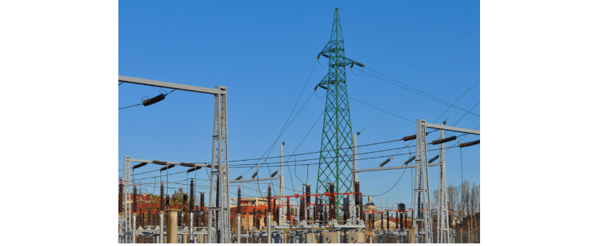
Taking the public network as an example, different wiring modes have significant differences in power supply utilization rate and reliability, mainly including single - ring network type, two - supply - and - one - standby, double - ring network type, multi - section N - connection, three - supply - and - one - standby, radial type, etc. Among them: the theoretical line utilization rate of the two - supply - and - one - standby mode is the highest at 2/3, and that of the three - supply - and - one - standby mode is 3/4, and both have high reliability; the theoretical utilization rate of the single - radial mode can reach 1, but the reliability is low; the double - ring network, multi - section N - connection, "2 - 1" and "3 - 1" modes have high reliability, but the theoretical utilization rates are 1/2, 1/2, and 2/3 respectively. Except for the single - radial mode, the rest all meet the N - 1 safety criterion. Therefore, it is necessary to select a wiring mode with a higher utilization rate in combination with the actual power supply reliability requirements.
2.2.2 Configure Reactive Power Compensation Equipment
In the power triangle, if the active power remains unchanged, a decrease in the power factor will lead to an increase in the reactive power demand. In actual operation, electrical equipment often needs to be expanded due to not reaching the rated power, which will reduce the utilization rate and increase the line loss. Therefore, it is necessary to reduce the redundant capacity of the equipment through reactive power compensation.
In practice, on - site compensation is the optimal method, which can reduce the reactive power transmission loss. However, there are safety and cost pressures in full implementation. It is recommended to combine the three methods of hierarchical compensation, centralized installation, and decentralized installation to avoid over - compensation.
2.3 Improve the Life Rate
Extend the effective service time of the equipment through real - time monitoring and full - life - cycle management:
2.3.1 Strengthen the Monitoring of Operational Status
Use quantitative indicators to evaluate the equipment status (for example, 1 represents the best and 0 represents the worst), and track the numerical fluctuations in real - time. If the value exceeds the set range or is lower than the threshold, immediately determine it as abnormal and arrange for maintenance or replacement.
2.3.2 Optimize the Management of the Operating Environment
The operation of the transformer is easily affected by environmental factors such as severe weather and temperature differences. It is necessary to comprehensively evaluate the surrounding environment to accurately judge the equipment status. At the same time, it is necessary to protect the equipment from excessive aging caused by factors such as temperature, humidity, and light through regular inspections (especially after extreme weather) to reduce losses.
2.3.3 Standardize the Decommissioning Management
Based on the equipment performance parameters and instruction manual, develop a monthly decommissioning plan, and strictly implement it in combination with the condition monitoring data. For the transformer determined to be decommissioned, a decommissioning opinion should be written, and internal procedures such as identification and review should be completed; for idle equipment that can be reused, it should be stored in a suitable environment, and a comprehensive inspection and trial operation are required before re - commissioning.
After confirming that the equipment is scrapped and completing the relevant procedures, the scrapped materials need to be evaluated, filed, and disposed of. The specific disposal methods include manufacturer recycling, compliance scrap trading, etc.


