What Are the Neutral-Point Grounding Modes and Protection Methods of Transformers in Power Grids?

Neutral - Point Grounding Modes and Protection of Transformers in Power Grids
For systems ranging from 110 kV to 500 kV, an effective grounding method shall be adopted. Specifically, under all operating conditions, the ratio of zero - sequence reactance to positive - sequence reactance X0/X1 of the system should be a positive value and not exceed 3. Meanwhile, the ratio of zero - sequence resistance to positive - sequence reactance R0/X1 should also be a positive value and not exceed 1.
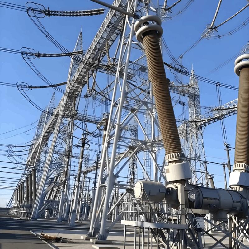
In 330 kV and 500 kV systems, the neutral points of transformers are directly grounded.
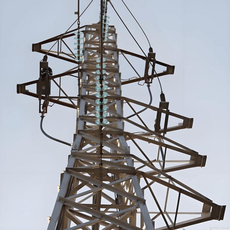
In 110 kV and 220 kV power grids, the neutral points of most transformers are directly grounded. For some transformers, their neutral points are grounded via gaps, surge arresters, or the parallel combination of gaps and surge arresters.
To limit the single - phase short - circuit current in the power grid, low - reactance grounding can be applied to the neutral points of transformers rated at 110 kV and above.
Neutral - Point Protection of 110 kV and 220 kV Transformers
To limit the single - phase grounding short - circuit current, avoid communication interference, and satisfy the requirements for the setting and configuration of relay protection, the neutral point of one transformer is directly grounded. For the remaining transformers, their neutral points are grounded through surge arresters, protection gaps, or the parallel connection of surge arresters and protection gaps.
Most transformers employ a protection scheme that combines surge arresters with discharge gaps. The discharge gap typically uses a rod - rod structure, and the majority of surge arresters are configured as zinc oxide surge arresters.

Protection Division for Parallel Gaps with Surge Arresters
Power frequency and switching overvoltages are handled by the gaps, while lightning and transient overvoltages are borne by the surge arresters. Simultaneously, the gaps serve to limit excessively high - amplitude power frequency overvoltages and overly high residual voltages that might occur on the surge arresters. This approach not only safeguards the neutral point of the transformer but also achieves mutual protection.
Protection by Metal Oxide Surge Arresters
When a single - phase grounding and loss - of - ground fault occurs, the resulting overvoltage may damage or even cause the explosion of the surge arrester.
Protection by Rod - Rod Gaps
This type of protection adopts a split - type installation. In practice, distance adjustment tends to be inaccurate, and concentricity is often poor. After discharge, the generated arc will erode the electrodes. Under lightning impulse, chopped waves are produced, which pose a threat to the insulation safety of equipment. The protection gap cannot self - extinguish the arc. Instead, relay protection is required to interrupt the arc, which may lead to misoperation of the relay protection.
Parallel Protection by Surge Arresters and Gaps
The coordination requirements among the protection level of the surge arrester, the operating characteristics of the rod gap, and the insulation level of the transformer’s neutral point are extremely stringent and difficult to achieve in practice.
Protection by Composite Gaps
Composite insulators are utilized for mechanical support. The high - voltage and low - voltage electrodes are fixed at both ends of the insulator, and the gap electrodes are in the shape of goat horns. Its discharge electrodes and arc - ignition electrodes are separated. It offers advantages such as good concentricity, accurate distance determination, convenient installation and commissioning, strong ablation resistance, and stable discharge voltage. It overcomes the inherent drawbacks of split - type installed rod gaps and is more suitable for protecting the neutral point of transformers.
Protection Principles
Under the action of lightning overvoltage, the gap should breakdown to protect the insulation of the transformer’s neutral point. Its lightning impulse discharge voltage should be coordinated with the lightning impulse withstand level of the transformer’s neutral point.
When a single - phase grounding fault occurs in the system, the neutral - point insulation should be able to withstand the overvoltage generated by the fault, and the gap should not breakdown to prevent misoperation of relay protection. When a single - phase grounding occurs in the system accompanied by neutral - point loss - of - ground, or when the system experiences non - full - phase operation, resonance faults, etc., leading to power frequency overvoltage exceeding a certain amplitude, the gap should breakdown to clamp the system’s neutral point and limit the overvoltage at the transformer’s neutral point.
Protection by Controllable Gaps
A controllable gap mainly consists of a fixed gap, a control gap, and a capacitor voltage - equalizing circuit. The goat - horn gap functions as the fixed gap, and a vacuum switch is used to control the automatic breakdown of the controllable gap.
The controllable gap is used in parallel with the surge arrester. Under lightning and transient overvoltages, the surge arrester operates to limit the overvoltage, and the controllable gap remains inactive. When a single - phase grounding fault occurs in the system, this overvoltage poses no threat to the neutral - point insulation, so the controllable gap does not operate.
When power frequency overvoltage occurs (such as single - phase grounding and loss - of - ground in an isolated ungrounded system or non - full - phase operation), the controllable gap activates to protect the insulation of the transformer’s neutral point and the surge arrester.
The controllable gap effectively resolves the issues existing in gaps, surge arresters, and the parallel protection of rod gaps and surge arresters. The parallel connection of the controllable gap and the surge arrester can effectively protect the neutral point of the transformer.