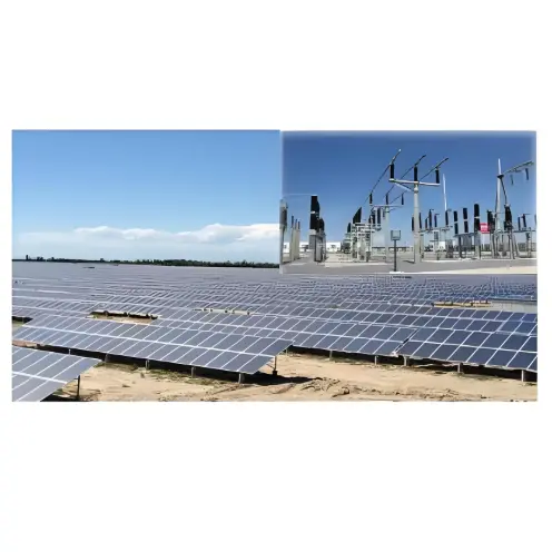
In grid-connected photovoltaic (PV) power generation systems, the step-up transformer is a critical component. Optimizing transformer selection to minimize inherent losses and enhance efficiency is essential for improving overall system performance. This article outlines key considerations for proper step-up transformer selection in PV systems.
Transformer Capacity Selection
The required transformer capacity is calculated as: Apparent Power = Active Power / Power Factor. Power factor requirements vary by region—typically 0.85 for construction and small industrial loads, and 0.9 for large industrial loads. For example, a 550 kW load at 0.85 power factor requires 550 / 0.85 = 647 kVA, so a 630 kVA transformer is suitable. Total load should not exceed 80% of the transformer’s rated capacity.
Transformer Voltage Selection
The primary winding voltage should match the source line voltage, while the secondary voltage must align with the connected equipment. For low-voltage three-phase four-wire distribution, appropriate voltage levels (e.g., 10 kV, 35 kV, or 110 kV) should be selected based on primary-side requirements.
Transformer Phase Selection
Choose between single-phase and three-phase configurations according to the power source and load requirements.
Transformer Winding Connection Group Selection
Three-phase windings can be connected in star (Y), delta (D), or zigzag (Z) configurations. The globally preferred connection for distribution transformers is Dyn11, which offers several advantages over Yyn0:
Harmonic Suppression: The delta (D) connection effectively suppresses higher-order harmonics.
Harmonic Circulation: Third harmonic currents circulate within the delta winding, neutralizing third harmonic flux from the low-voltage side.
Harmonic Containment: Third harmonic EMF in the high-voltage winding remains confined within the delta loop, preventing injection into the public grid.
Lower Zero-Sequence Impedance: Dyn11 transformers exhibit significantly lower zero-sequence impedance, aiding in the clearance of low-voltage single-phase ground faults.
Superior Neutral Current Handling: Capable of handling neutral currents exceeding 75% of phase current, making them ideal for unbalanced loads.
Continuity Under Phase Loss: If one high-voltage fuse blows, the remaining two phases can continue operating with Dyn11, unlike with Yyn0.
Therefore, Dyn11-connected transformers are strongly recommended.
Load Loss, No-Load Loss, and Impedance Voltage
Due to the daytime operation pattern of PV systems, transformers incur no-load losses whenever energized, regardless of output. Minimizing load losses is crucial; if nighttime operation occurs, low no-load losses are also important.
This selection strategy ensures efficient transformer operation within PV systems, reducing overall losses and enhancing power generation performance.