• Product
  • Suppliers
  • Manufacturers
  • Solutions
  • Free tools
  • Knowledges
  • Experts
  • Communities
Search


Why Does MVDC Grounding Cause System Faults?

Felix Spark
Felix Spark
Field: Failure and maintenance
China

Analysis and Handling of DC System Grounding Faults in Substations

When a DC system grounding fault occurs, it can be classified as single-point grounding, multi-point grounding, loop grounding, or reduced insulation. Single-point grounding is further divided into positive-pole and negative-pole grounding. Positive-pole grounding may cause misoperation of protection and automatic devices, while negative-pole grounding may lead to failure to operate (e.g., relay protection or tripping devices). Once any ground fault exists, it forms a new ground path; it must be eliminated promptly. Otherwise, if a second or additional ground develops, it may lead to serious faults or accidents.

Under normal operation, the insulation resistance of both positive and negative poles of the DC system to ground is 999 kΩ. However, when outdoor equipment becomes damp, the DC system’s insulation resistance decreases. The alarm threshold for a 220V DC system is typically 25 kΩ, and 15 kΩ for a 110V system. State Grid Hubei Maintenance Company places high importance on grounding hidden dangers and has raised the alarm standard: a warning is triggered when insulation drops to 40 kΩ for 220V systems and 25 kΩ for 110V systems. This allows隐患 to be eliminated before insulation degradation develops into a full ground fault.

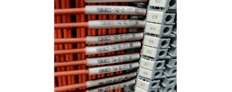
Grounding Cable Inside the DC Panel.jpg

Recently, due to prolonged severe weather and extended plum rain season with high humidity, six 500 kV substations in the province have experienced varying degrees of reduced DC insulation or direct grounding:

  • Enshi and Anfu: insulation dropped to 40 kΩ

  • Shuanghe: positive-pole grounding

  • Jiangxia: positive-pole grounding

  • Junshan: overall insulation reduction

  • Xian Nv Shan: insulation drop, negative-to-ground at 18 kΩ

  • Xinglong: positive-pole grounding

Case Analysis of Recent DC System Insulation Issues:

(1) 500 kV Enshi & Anfu Substations:
DC insulation monitoring devices showed insulation dropping to 40 kΩ. After observation, insulation partially recovered to an acceptable range. Based on past experience, the likely cause was moisture ingress in the thermal relay within outdoor disconnect switch mechanism enclosures.

(2) 500 kV Jiangxia Substation:
After a DC ground fault, secondary maintenance personnel checked the insulation monitor and found no abnormal signals. Field voltage measurements showed 0 V on the positive pole to ground. Using a DC grounding detector, the fault was traced to a moisture-affected contact in the density relay of the #2 bus tie control cabinet. After removing the faulty contact, the DC system insulation returned to normal.

Challenges in DC Grounding Troubleshooting:
Locating and handling DC grounding defects is challenging. Faults often recur with weather changes, and fault points are difficult to identify. Multi-point grounding can also occur. Most recent grounding issues were caused by reduced insulation in outdoor equipment contacts or cables. Contributing factors include aging components with degraded insulation and prolonged rain causing moisture ingress or equipment failure.

Enhancing DC Grounding Response Capability:
Effective handling requires coordinated efforts, standardized procedures, and integration of operation and maintenance (O&M) systems:

  • Safety Procedures:
    Before handling a DC ground fault, clear all personnel from relevant areas, especially those working on secondary circuits. At least two personnel must be present during fault location and repair. Prevent accidental DC short circuits or additional grounding. Implement safety measures to avoid protection misoperations.

  • Fault Location Strategy:
    Follow the principles: microprocessor-based detection first, then manual; external before internal; secondary before primary; signals before control. First, use the DC insulation monitoring device to locate the fault. If data is inaccurate, proceed with manual inspection.

  • Rapid Response Protocol:
    O&M staff must immediately collect alarm messages and abnormal signals from the insulation monitor. Secondary teams should quickly organize emergency repairs. If the monitor accurately identifies the faulty circuit, disconnect its power and observe if insulation recovers. If not, use a DC grounding detector to scan all DC circuits, identify suspect circuits, and test by power disconnection.

  • Precise Fault Isolation:
    Once the faulty circuit is identified, use schematics to pinpoint potential grounding points. Test by disconnecting suspected terminals. After confirmation, apply reliable insulation isolation. Coordinate closely with primary equipment teams to eliminate the fault promptly.

Preventive Measures to Reduce DC Grounding Incidents:

  • Improve operating environments. Install air conditioning in areas with inadequate temperature control. Seal terminal boxes, switch mechanism enclosures, and disconnect switch enclosures properly. Ensure cabinet doors are rainproof.

  • During regular inspections or transformer installations, thoroughly check whether gas relays, oil flow relays, oil level gauges, thermometers, and pressure relief devices have proper rain shields. Verify secure wiring box installation, presence of sealing gaskets, and that secondary cables are properly routed and undamaged.

  • Use scheduled outages to replace vulnerable outdoor secondary components that are frequently operated or continuously energized.

  • Eliminate design flaws or poor workmanship. Ensure secondary circuits are complete during commissioning—avoid parasitic circuits, loops, or crossovers. Pay attention to cleaning and dust removal during protection and automatic device inspections.

  • For technical upgrades or new construction, strictly follow design drawings. Conduct thorough pre-construction drawing reviews. Prevent DC I/II segment mixing, AC/DC mixing, and parasitic circuits that could cause DC system anomalies.

  • Strengthen operation, maintenance, and inspection of DC systems, DC distribution panels, and insulation monitoring devices across all substations. Ensure monitoring devices accurately reflect grounding locations, enabling rapid isolation by maintenance personnel.

Give a tip and encourage the author!
Recommended
35kV Distribution Line Single-Phase Ground Fault Handling
Distribution Lines: A Key Component of Power SystemsDistribution lines are a major component of power systems. On the same voltage-level busbar, multiple distribution lines (for input or output) are connected, each with numerous branches arranged radially and linked to distribution transformers. After being stepped down to low voltage by these transformers, electricity is supplied to a wide range of end users. In such distribution networks, faults such as phase-to-phase short circuits, overcurre
Encyclopedia
10/23/2025
MVDC: Future of Efficient, Sustainable Power Grids
The Global Energy Landscape Is Undergoing a Fundamental Transformation toward a "fully electrified society," characterized by widespread carbon-neutral energy and the electrification of industry, transportation, and residential loads.In today’s context of high copper prices, critical mineral conflicts, and congested AC power grids, Medium-Voltage Direct Current (MVDC) systems can overcome many limitations of traditional AC networks. MVDC significantly enhances transmission capacity and efficienc
Edwiin
10/21/2025
Grounding Causes of Cable Lines and the Principles of Incident Handling
Our 220 kV substation is located far from the urban center in a remote area, surrounded primarily by industrial zones such as Lanshan, Hebin, and Tasha Industrial Parks. Major high-load consumers in these zones—including silicon carbide, ferroalloy, and calcium carbide plants—account for approximately 83.87% of our bureau’s total load. The substation operates at voltage levels of 220 kV, 110 kV, and 35 kV.The 35 kV low-voltage side mainly supplies feeders to ferroalloy and silicon carbide plants
Felix Spark
10/21/2025
Overhead Power Lines & Towers: Types, Design & Safety
Besides ultra-high voltage AC substations, what we encounter more frequently are power transmission and distribution lines. Tall towers carry conductors that leap across mountains and seas, stretching into the distance before reaching cities and villages. This is also an interesting topic—today, let's explore transmission lines and their supporting towers.Power Transmission and DistributionFirst, let’s understand how electricity is delivered. The electric power industry primarily consists of fou
Encyclopedia
10/21/2025
Send inquiry
Download
Get the IEE Business Application
Use the IEE-Business app to find equipment, obtain solutions, connect with experts, and participate in industry collaboration anytime, anywhere—fully supporting the development of your power projects and business.