• Product
  • Suppliers
  • Manufacturers
  • Solutions
  • Free tools
  • Knowledges
  • Experts
  • Communities
Search


High harmonics? Your transformer may be overheating and aging fast.

Leon
Leon
Field: Fault Diagnosis
China

This report is based on the analysis of one-day power quality monitoring data of your company's distribution system. The data shows that there is significant three-phase current harmonic distortion in the system (with a high total harmonic distortion of current, THDi). In accordance with international standards (IEC/IEEE), harmonic currents at this level have posed substantial risks to the safe, reliable, and economical operation of the power supply transformer, mainly manifested in additional heat generation, service life reduction, and even transformer damage.

1. Overview of Test Data

  • Monitored Parameter: Total Harmonic Distortion of Three-Phase Current (A THD[50] Avg [%] L1, L2, L3)

  • Monitoring Duration: 4:00 p.m. on September 8, 2025 to 8:00 a.m. on September 9, 2025 (Rwanda Time)

Total Harmonic Distortion of Three-Phase Current.jpg

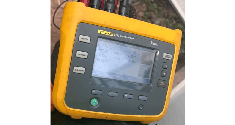
Data Source: FLUKE 1732 Power Logger

FLUKE 1732 Power Logger.jpg

  • During the monitoring period, the total harmonic distortion of three-phase current (THDi) remained at a high level (e.g., consistently around 60%).

  • This harmonic level significantly exceeds the recommended good practice range (THDi < 5%) and the general allowable range (THDi < 8%) for distribution systems specified in international standards such as IEEE 519-2014 and IEC 61000-2-2.

2. Mechanism of Harmonic Current Impact on Transformers (Problem Analysis)

Transformers are designed based on pure 50Hz sinusoidal current. Harmonic currents (especially the 3rd, 5th, and 7th harmonics) cause two core issues:

  • Doubled Eddy Current Loss: The eddy current loss in transformer windings is proportional to the square of the current frequency. High-frequency harmonic currents lead to a sharp increase in eddy current loss, far exceeding the design value based on fundamental current.

  • Additional Heat Generation and Thermal Stress: The aforementioned extra losses are converted into heat, resulting in abnormal temperature rises in transformer windings and iron cores.

3. Risk Assessment Based on International Standards

In accordance with the provisions of IEC 60076-1 and IEEE Std C57.110 regarding transformer operation under non-sinusoidal current, the main risks posed by the current harmonic level to your transformer include:

  • Risk 1: Accelerated Insulation Aging and Severe Service Life ReductionThe service life of a transformer is directly determined by its operating temperature. The rule of thumb indicates that for every continuous 6-10°C increase in winding temperature, the insulation aging rate doubles, and the expected service life of the transformer is halved accordingly. Long-term overheating will cause the transformer insulation to become brittle, eventually leading to breakdown faults.

  • Risk 2: Reduced Actual Load-Carrying Capacity (Derating Required)To avoid overheating, the transformer cannot operate at its rated capacity under the current harmonic level. According to the calculation method in IEEE Std C57.110, the transformer must be derated (for example, when THDi is 12%, the derating factor may need to be 0.92 or lower). This means that a transformer with a rated capacity of 1000kVA may have an actual safe load-carrying capacity of less than 920kVA, limiting the system's capacity expansion potential.

  • Risk 3: Increased Transformer Field StrengthAccording to the electromotive force formula Et = 4.44 ⋅f⋅Φm (where f is frequency), harmonics generate high-frequency magnetic flux, which induces significant eddy currents in the winding conductors, leading to local hot spots and overheating. The over-frequency of harmonics acts as an "amplifier" — even if the amplitude of the harmonic magnetic flux Φmh is small, its high-frequency characteristic will amplify the induced turn-to-turn electromotive force by h times. This amplified electromotive force is applied to the winding insulation, especially the first few turns of the coil, causing local overvoltage and greatly increasing the risk of insulation breakdown.

Give a tip and encourage the author!
Recommended
What Are Combined Transformer Standards? Key Specs & Tests
Combined Instrument Transformers: Technical Requirements and Testing Standards Explained with DataA combined instrument transformer integrates a voltage transformer (VT) and a current transformer (CT) into a single unit. Its design and performance are governed by comprehensive standards covering technical specifications, testing procedures, and operational reliability.1. Technical RequirementsRated Voltage:The primary rated voltages include 3kV, 6kV, 10kV, and 35kV, among others. The secondary v
Edwiin
10/23/2025
Why Upgrade to Maintenance-Free Transformer Breathers?
Maintenance-Free Moisture Absorption Technology for Oil-Immersed TransformersIn traditional oil-filled transformers, the temperature control system causes thermal expansion and contraction of insulating oil, requiring the sealing gel chamber to absorb significant moisture from the air above the oil surface. The frequency of manual silica gel replacement during patrols directly impacts equipment safety—delayed replacement can easily lead to oil degradation. Maintenance-free moisture absorbers rev
Felix Spark
10/23/2025
What Is an MVDC Transformer? Key Applications & Benefits Explained
Medium-voltage DC (MVDC) transformers have a wide range of applications in modern industry and power systems. The following are some key application areas for MVDC transformers: Power Systems: MVDC transformers are commonly used in high-voltage direct current (HVDC) transmission systems to convert high-voltage AC into medium-voltage DC, enabling efficient long-distance power transmission. They also contribute to grid stability control and power quality improvement. Industrial Applications: In in
Edwiin
10/23/2025
How to Improve Rectifier Transformer Efficiency? Key Tips
Optimization Measures for Rectifier System EfficiencyRectifier systems involve numerous and diverse equipment, so many factors affect their efficiency. Therefore, a comprehensive approach is essential during design. Increase Transmission Voltage for Rectifier LoadsRectifier installations are high-power AC/DC conversion systems requiring substantial power. Transmission losses directly impact rectifier efficiency. Increasing the transmission voltage appropriately reduces line losses and improves r
James
10/22/2025
Related Products
Send inquiry
Download
Get the IEE Business Application
Use the IEE-Business app to find equipment, obtain solutions, connect with experts, and participate in industry collaboration anytime, anywhere—fully supporting the development of your power projects and business.