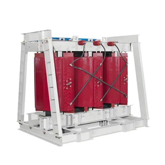
1. Oil-Immersed Self-Cooling (ONAN)
The working principle of oil-immersed self-cooling is to transfer the heat generated inside the transformer to the surface of the tank and cooling tubes through natural convection of the transformer oil. The heat is then dissipated into the surrounding environment via air convection and thermal conduction. This cooling method does not require any dedicated cooling equipment.
Applicable to:
Products with capacity up to 31,500 kVA and voltage level up to 35 kV;
Products with capacity up to 50,000 kVA and voltage level up to 110 kV.
2. Oil-Immersed Forced-Air Cooling (ONAF)
Oil-immersed forced-air cooling is based on the principle of ONAN, with the addition of fans mounted on the tank surface or cooling tubes. These fans enhance heat dissipation by forced air flow, increasing the transformer’s capacity and load-carrying capability by nearly 35%. During operation, losses such as iron loss, copper loss, and other forms of heat are generated. The cooling process is as follows: First, heat is transferred by conduction from the core and windings to their surfaces and into the transformer oil. Then, through natural oil convection, the heat is continuously transferred to the inner walls of the tank and radiator tubes. Next, heat is conducted to the outer surfaces of the tank and radiators. Finally, the heat is dissipated into the surrounding air via air convection and thermal radiation.
Applicable to:
35 kV to 110 kV, 12,500 kVA to 63,000 kVA;
110 kV, below 75,000 kVA;
220 kV, below 40,000 kVA.
3. Forced-Oil Circulation Forced-Air Cooling (OFAF)
Applicable to transformers with capacity from 50,000 to 90,000 kVA and voltage level of 220 kV.
4. Forced-Oil Circulation Water Cooling (OFWF)
Mainly used for step-up transformers in hydroelectric power plants, applicable to transformers with voltage level 220 kV and above and capacity 60 MVA and above.
The working principle of forced-oil circulation cooling and forced-oil circulation water cooling is the same. When a main transformer adopts forced oil circulation cooling, oil pumps drive the oil through the cooling circuit. The oil cooler is specially designed for efficient heat dissipation, often assisted by electric fans. By increasing the oil circulation speed threefold, this method can boost the transformer’s capacity by approximately 30%. The cooling process involves submersible oil pumps directing oil into ducts between the core or windings to carry away heat. The hot oil from the top of the transformer is then extracted by a pump, cooled in the cooler, and returned to the bottom of the oil tank, forming a forced oil circulation loop.
5. Forced-Oil Directed Circulation Forced-Air Cooling (ODAF)
Applicable to:
75,000 kVA and above, 110 kV;
120,000 kVA and above, 220 kV;
330 kV class and 500 kV class transformers.
6. Forced-Oil Directed Circulation Water Cooling (ODWF)
Applicable to:
75,000 kVA and above, 110 kV;
120,000 kVA and above, 220 kV;
330 kV class and 500 kV class transformers.
Components of a Forced-Oil Forced-Air Cooling Transformer Cooler
Traditional power transformers are equipped with manually controlled fan systems. Each transformer typically has six sets of cooling motors requiring centralized control. Fan operation relies on thermal relays, with their power circuits controlled by contactors. Fans are started or stopped based on transformer oil temperature and load conditions through logical judgment.
These traditional control systems require significant manual intervention and have notable drawbacks: all fans start and stop simultaneously, resulting in high inrush currents that may damage circuit components. When oil temperature ranges between 45°C and 55°C, it is common practice to run all fans at full capacity, leading to significant energy waste and increased maintenance challenges. Traditional cooling control systems mainly use relays, thermal relays, and contact-based logic circuits. The control logic is complex, and frequent switching of contactors may cause contact burning. Moreover, fans often lack essential protections such as overload, phase loss, and undervoltage protection, reducing operational reliability and increasing maintenance costs.
Functions of the Transformer Tank and Cooling System
The transformer tank serves as the outer enclosure, housing the core, windings, and transformer oil, while also providing some heat dissipation capability.
The transformer cooling system creates oil circulation driven by the temperature difference between the upper and lower layers of oil. Hot oil flows through a heat exchanger where it is cooled and then returned to the bottom of the tank, effectively reducing the oil temperature. To enhance cooling efficiency, methods such as air cooling, forced-oil forced-air cooling, or forced-oil water cooling can be employed.