• Product
  • Suppliers
  • Manufacturers
  • Solutions
  • Free tools
  • Knowledges
  • Experts
  • Communities
Search


What Is a Main Transformer Its Working Principle Components and Applications?

Rockwell
Field: Manufacturing
China

Main Transformer

The main transformer is primarily responsible for converting the high-voltage electrical energy generated at power plants into lower-voltage electrical energy suitable for transmission, distribution, and end-use. This process involves stepping down voltage from high to low levels.

Working Principle

The main transformer operates based on the principles of electromagnetic induction and voltage transformation. When an alternating current (AC) is applied to the high-voltage winding, it generates an alternating magnetic flux in the core. This varying magnetic field is transferred through the core to the low-voltage winding. According to Faraday's law of electromagnetic induction, the changing magnetic flux induces an electromotive force (EMF) in the low-voltage winding, thereby achieving the conversion of electrical energy from high voltage to low voltage.
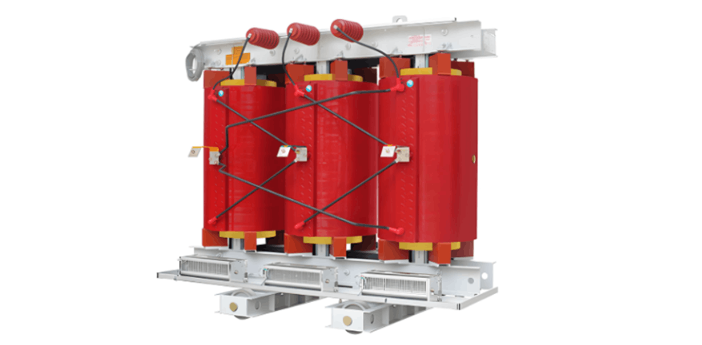
Components

The main transformer consists of several key components: the core, oil tank and cover, protective devices, cooling system, and bushings. The core assembly, which performs the electromagnetic energy conversion, includes the iron core, windings, leads, and insulation. The oil tank and cover comprise the tank body, top cover, base, and associated accessories such as oil sampling valves, drain plugs, and grounding bolts. Protective devices include the conservator, oil level gauge, oil purifier, flow relay, desiccant breather, and signal thermometer.

Applications

Main transformers are widely used across the three major stages of the power system: transmission, distribution, and utilization. They also find extensive applications in industrial facilities, construction sites, and residential areas, including use in power machinery, welding equipment, arc furnaces, power supply and distribution systems, and indoor lighting systems.

Give a tip and encourage the author!

Recommended

HECI GCB for Generators – Fast SF6 Circuit Breaker
1.Definition and Function1.1 Role of the Generator Circuit BreakerThe Generator Circuit Breaker (GCB) is a controllable disconnect point located between the generator and the step-up transformer, serving as an interface between the generator and the power grid. Its primary functions include isolating generator-side faults and enabling operational control during generator synchronization and grid connection. The operating principle of a GCB is not significantly different from that of a standard c
01/06/2026
Design Principles for Pole-Mounted Distribution Transformers
Design Principles for Pole-Mounted Distribution Transformers(1) Location and Layout PrinciplesPole-mounted transformer platforms should be located near the load center or close to critical loads, following the principle of “small capacity, multiple locations” to facilitate equipment replacement and maintenance. For residential power supply, three-phase transformers may be installed nearby based on current demand and future growth projections.(2) Capacity Selection for Three-Phase Pole-Mounted Tr
12/25/2025
Transformer Noise Control Solutions for Different Installations
1.Noise Mitigation for Ground-Level Independent Transformer RoomsMitigation Strategy:First, conduct a power-off inspection and maintenance of the transformer, including replacing aged insulating oil, checking and tightening all fasteners, and cleaning dust from the unit.Second, reinforce the transformer foundation or install vibration isolation devices—such as rubber pads or spring isolators—selected based on the severity of vibration.Finally, strengthen sound insulation at weak points of the ro
12/25/2025
Risk Identification and Control Measures for Distribution Transformer Replacement Work
1.Electric Shock Risk Prevention and ControlAccording to typical design standards for distribution network upgrades, the distance between the transformer’s drop-out fuse and the high-voltage terminal is 1.5 meters. If a crane is used for replacement, it is often impossible to maintain the required minimum safety clearance of 2 meters between the crane boom, lifting gear, slings, wire ropes, and the 10 kV live parts, posing a severe risk of electric shock.Control Measures:Measure 1:De-energize th
12/25/2025
Send inquiry
+86
Click to upload file

IEE Business will not sell or share your personal information.

Download
Get the IEE Business Application
Use the IEE-Business app to find equipment, obtain solutions, connect with experts, and participate in industry collaboration anytime, anywhere—fully supporting the development of your power projects and business.