MHD Generation or Magneto Hydro Dynamic Power Generation

03/19/2024

WechatIMG1744.jpeg

The MHD generation or, also known as magneto hydrodynamic power generation is a direct energy conversion system which converts the heat energy directly into electrical energy, without any intermediate mechanical energy conversion, as opposed to the case in all other power generating plants. Therefore, in this process, substantial fuel economy can be achieved due to the elimination of the link process of producing mechanical energy and then again converting it to electrical energy.

History of MHD Generation

The concept of MHD power generation was introduced for the very first time by Michael Faraday in the year 1832 in his Bakerian lecture to the Royal Society. He in fact carried out an experiment at the Waterloo Bridge in Great Britain for measuring the current, from the flow of the river Thames in earth’s magnetic field.

This experiment in a way outlined the basic concept behind MHD generation over the years then, several research work had been conducted on this topic, and later in August 13, 1940 this concept of magneto hydro dynamic power generation, was imbibed as the most widely accepted process for the conversion of heat energy directly into electrical energy without a mechanical sub-link.

Principle of MHD Generation

The principal of MHD power generation is very simple and is based on Faraday’s law of electromagnetic induction, which states that when a conductor and a magnetic field moves relative to each other, then voltage is induced in the conductor, which results in flow of current across the terminals.
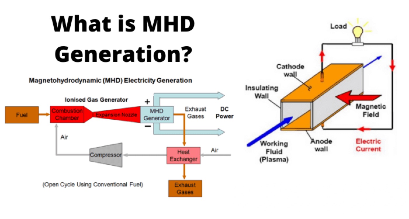
As the name implies, the magneto hydro dynamics generator shown in the figure below, is concerned with the flow of a conducting fluid in the presence of magnetic and electric fields. In conventional generator or
alternator, the conductor consists of copper windings or stripswhile in an MHD generator the hot ionized gas or conducting fluid replaces the solid conductor.

A pressurized, electrically conducting fluid flows through a transverse magnetic field in a channel or duct. Pair of electrodes are located on the channel walls at right angle to the magnetic field and connected through an external circuit to deliver power to a load connected to it. Electrodes in the MHD generator perform the same function as brushes in a conventional DC generator. The MHD generator develops DC power and the conversion to AC is done using an inverter.
The power generated per unit length by MHD generator is approximately given by,
WechatIMG1745.png

Where, u is the fluid velocity, B is the magnetic flux density, σ is the electrical conductivity of conducting fluid and P is the density of the fluid.

It is evident from the equation above, that for the higher power density of an MHD generator there must be a strong magnetic field of 4-5 tesla and high flow velocity of conducting fluid besides adequate conductivity.

MHD Cycles and Working Fluids

The MHD cycles can be of two types, namely

  1. Open Cycle MHD.

  2. Closed Cycle MHD.

The detailed account of the types of MHD cycles and the working fluids used, are given below.

Open Cycle MHD System

In open cycle MHD system, atmospheric air at very high temperature and pressure is passed through the strong magnetic field. Coal is first processed and burnet in the combustor at a high temperature of about 2700oC and pressure about 12 ATP with pre-heated air from the plasma. Then a seeding material such as potassium carbonate is injected to the plasma to increase the electrical conductivity. The resulting mixture having an electrical conductivity of about 10 Siemens/m is expanded through a nozzle, so as to have a high velocity and then passed through the magnetic field of MHD generator. During the expansion of the gas at high temperature, the positive and negative ions move to the electrodes and thus constitute an electric current. The gas is then made to exhaust through the generator. Since the same air cannot be reused again hence it forms an open cycle and thus is named as open cycle MHD.

Closed Cycle MHD System

As the name suggests the working fluid in a closed cycle MHD is circulated in a closed loop. Hence, in this case inert gas or liquid metal is used as the working fluid to transfer the heat. The liquid metal has typically the advantage of high electrical conductivity, hence the heat provided by the combustion material need not be too high. Contrary to the open loop system there is no inlet and outlet for the atmospheric air. Hence, the process is simplified to a great extent, as the same fluid is circulated time and again for effective heat transfer.

Advantages of MHD Generation

The advantages of MHD generation over the other conventional methods of generation are given below.

  1. Here only working fluid is circulated, and there are no moving mechanical parts. This reduces the mechanical losses to nil and makes the operation more dependable.

  2. The temperature of working fluid is maintained by the walls of MHD.

  3. It has the ability to reach full power level almost directly.

  4. The price of MHD generators is much lower than conventional generators.

  5. MHD has very high efficiency, which is higher than most of the other conventional or non-conventional method of generation.

Statement: Respect the original, good articles worth sharing, if there is infringement please contact delete.

Hello,I'm Wdwiin. A decade of hands-on experience in electrical engineering, specializing in high-voltage systems, smart grids, and renewable energy technologies. Passionate about technical exchange and knowledge sharing, committed to interpreting industry trends with professional insights to empower peers. Connection creates value—let’s explore the boundless possibilities of the electrical world together!

What is the difference between a dielectric and an insulator?
Dielectrics and insulators are distinguished primarily by their applications. One of the main differences is that a dielectric can store electrical energy by becoming polarized in an electric field, whereas an insulator resists the flow of electrons to prevent current conduction. Other key differences between them are outlined in the comparison chart below.Definition of DielectricA dielectric material is a type of insulator that contains few or no free electrons. When subjected to an electric fi
08/30/2025
What losses occur during operation of the transformer? How to reduce losses?
Transformers experience various types of losses during operation, primarily categorized into two main types: copper losses and iron losses.Copper LossesCopper losses, also known as I²R losses, are caused by the electrical resistance of the transformer windings—typically made of copper. As current flows through the windings, energy is dissipated in the form of heat. These losses are proportional to the square of the load current (I²R), meaning they increase significantly with high
Rockwell
08/29/2025
Cable Fault Detection, Testing, Location and Repair
I. Methods for Cable Testing and Inspection:Insulation Resistance Test: Use an insulation resistance tester to measure the insulation resistance value of the cable. A high insulation resistance value indicates good insulation, while a low value may suggest insulation problems requiring further investigation.Voltage Withstand Test: Apply a high-voltage test using a high-voltage tester to verify whether the cable can withstand high voltage under its rated operating conditions. Under normal circums
08/29/2025
Cable Quality Inspection and Cable Detection & Testing
Power cable quality inspection and cable testing are conducted to ensure that the cable's quality and performance meet specified requirements, thereby guaranteeing the safe and stable operation of power systems. Below are some common contents of power cable quality inspection and cable testing:Visual Inspection: Check the cable surface for physical defects such as damage, deformation, or scratches to ensure the cable's exterior is intact.Dimensional Measurement: Measure dimensional parameters su
08/29/2025
Inquiry
Download
IEE-Business is dedicated to serving the personnel in the global power industry.
Join IEE-Business, not only can you discover power equipment and power knowledge, but also canhnd like - minded friends!