

Cihazên ku dêwarê reaktîf a sîsteman pêşand bibin vebijêrên varmeter nîne. Dêwar reaktîf çi ye? Dêwar reaktîf a sîstemê bi rêzikê VIsinA taybet dihê.
Li vir navçeya fizîkî ya dêwarê reaktîf anîn, her çewtiqek matematîkî pişast. Pirsgirêka dêwarê reaktîf pêdivî ye cema li viriyê dêwarê reaktîf a sîstemê zaf be, factorê elektrîk da kev be û hêza zêdetir bike. Li ser şertê berdestkirina dêware, varmeters dikarin wek hejmara bikin
Varmeters ên phase yek
Varmeters ên phase çend.
Dikarin dikarin divêr jinsên varmeters bin gotin.
Li vir jinsa varmeteran de, presiya werin dibas kirin ku bibe inductively bêtir û ku voltage across the pressure coil lead by the pressure coil current by angle of 90o. Cûr current îro load current e ku difa angle A yê supply voltage yê. Qeydê varmetera wekheya bi rêzikê
ku matematîkî yên dêwarê reaktîf a sîstemê.
Di vir de circuit diagram a varmeter ên phase yek.
Hêzbijêrin dikarin phasor diagram bikin ji bo vir circuit bi axis reference as voltage axis.
Current a pressure coil voltage lags bi angle 90o ku di phasor diagram de derbas dihat.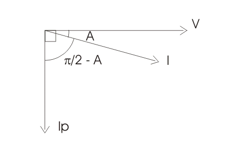
Niha hêvek demerên bikarhêneriya varmetera wê niha dêwarê reaktîf hatine pêşand ne ku harmonics harmonics hemîn.
Du auto-transformers bikaranîn bi talîna phase shifting (ku pêdivî ye ji bo pêşandina dêware reaktîf), ji bo connected li ser open delta configuration. Current coils of both the wattmeter connected in series with supply line 1 and 3.
While pressure coils are connected in parallel as shown in the diagram given below-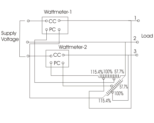
Both the auto-transformers can produce maximum of 115.4% of the line voltage as marked in the diagram. Tapping on both the transformers are given at 57.7%, 100% and 115.4%. One of the end of the pressure coil of wattmeter (marked as one) is connected to 115.4 % of tapping of auto-transformer-2 while other end is connected to 57.7 % tapping of auto-transformer-1. Due to this connection voltage produces across the pressure coil of wattmeter one is equal to line voltage but shifted by an angle of 90o. The power shown by wattmeter thus equal to reactive power. Similarly the pressure coil of wattmeter 2 is connected showing same voltage equal to line voltage but differ in phase and this difference in phase is equal to again 90o. Now the arithmetic sum of both readings of the wattmeters is equal to total reactive power of circuit.
Note that reactive power in three phase balanced circuit can be measured by single wattmeter method. This circuit diagram is shown below-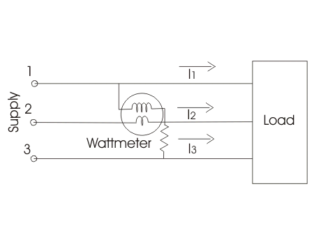
The current coil is connected in series with line 2 as shown in the diagram. The pressure coil is connected between the line 1 and line 2. The reading of the wattmeter will measure the reactive power.
Statement: Respect the original, good articles worth sharing, if there is infringement please contact delete.


