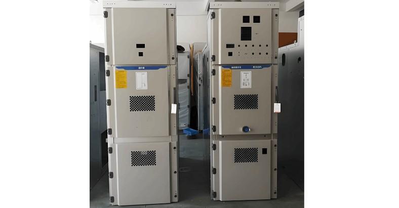
Currently, China's medium-voltage distribution networks predominantly operate at 10kV. With rapid economic development, power loads have surged, increasingly exposing the limitations of the existing power supply methods. Due to the outstanding advantages of 24kV high-voltage switchgear in meeting higher load capacity demands, it has quietly gained traction within the industry. Following the State Grid Corporation's "Notice on Promoting the 20kV Voltage Level," the 20kV voltage class has seen a rapid rise in adoption.
As a critical product for this voltage level, the structure and insulation design of 24kV high-voltage switchgear have become focal points in the industry. According to the power industry standard "Common Technical Requirements for High-Voltage Switchgear and Control Equipment" (DL/T 593-2006), specific insulation requirements for switchgear are clearly defined. The insulation requirements for 24kV products are as follows:
Minimum air clearance (phase-to-phase, phase-to-ground): 180mm; Power frequency withstand voltage (phase-to-phase, phase-to-ground): 50/65 kV/min, (across isolation joints): 64/79 kV/min; Lightning impulse withstand voltage (phase-to-phase, phase-to-ground): 95/125 kV/min, (across isolation joints): 115/145 kV/min.
Note: Data on the left side of the slash applies to solidly grounded neutral systems, while data on the right applies to systems with neutral grounded through an arc suppression coil or ungrounded.
24kV high-voltage switchgear can be categorized by insulation method into air-insulated metal-enclosed switchgear and gas-insulated SF6 ring main units. Air-insulated metal-enclosed switchgear for 24kV, particularly the mid-mounted withdrawable type (hereinafter referred to as the 24kV mid-mounted switchgear), has become a key design focus. This article discusses several recommendations regarding the structure and insulation design of 24kV mid-mounted switchgear and gas-insulated SF6 ring main units, offered for reference and comment.
1. Design of 24kV Mid-Mounted Switchgear
The technology for 24kV mid-mounted switchgear primarily comes from three sources: First, an upgrade from the 12kV KYN28-12 product by directly replacing components related to insulation. Second, foreign mid-mounted products entering the domestic market, such as those from ABB and Eaton Senyuan. Third, independently developed 24kV mid-mounted switchgear within China. The third category, designed specifically for China's existing technical conditions and requirements, is the most competitive in the market. Therefore, during its design, the overall product structure and insulation design must be fully considered, as detailed below:
1.1 Equal-Height Cabinet Structure and Triangular Busbar Arrangement
Most 12kV mid-mounted switchgear uses a structure that is higher in the front and lower in the rear, with the three-phase busbars arranged in a triangular (delta) configuration, and the instrument compartment as a removable, independent structure. If this method is used for 24kV mid-mounted switchgear, it clearly cannot meet the minimum air clearance requirement of 180mm. Therefore, the 24kV mid-mounted switchgear should adopt an equal-height cabinet design, with the instrument compartment integrated into the main cabinet.
The cabinet height should be appropriately increased to 2400mm, providing more space for the busbar and circuit breaker compartments. The busbar wall bushings should be arranged in a triangular configuration. This approach not only meets the air clearance requirements but also effectively suppresses and withstands electromagnetic forces, improves busbar heat dissipation, and enhances insulation reliability.
1.2 Rational Design of Switchgear Width
From the perspective of insulation reliability, air insulation is the most reliable method; as long as the minimum insulation clearance is guaranteed, insulation can be fully assured. Considering a fully air-insulated design, the theoretical width of a 24kV switchgear should be 1020mm. However, in actual production, most manufacturers choose a cabinet width of 1000mm, which necessitates the use of composite insulation. Generally, heat-shrink tubing is applied to the busbars, and SMC (Sheet Molding Compound) insulating barriers are installed between phases and between phase and ground to enhance insulation.
1.3 Design for Uniform Electric Field Distribution
Testing proves that the higher the voltage level, the higher the local electric field strength during power frequency withstand voltage tests, sometimes accompanied by noticeable corona discharge sounds. According to regulations, as long as no disruptive discharge occurs, the test is considered passed. However, high local electric field strength can affect the product's ability to withstand overvoltages during normal operation.
Therefore, product design should prioritize achieving as uniform an electric field distribution as possible, avoiding localized field concentration. From practical experience, shaping conductors to achieve a uniform field is effective. For the cut ends of busbars, use a forming milling cutter to machine the ends into rounded corners. For the busbar ends inside the contact box, first form them into a semi-circular shape, then mill them into a rounded corner. Where conditions allow, install a metal shielding cover outside the circuit breaker's plum blossom contacts, or embed a metal shielding mesh during the casting of the contact box. These measures can effectively uniform the electric field distribution, suppress field peaks, and further improve insulation levels.
1.4 Use of Insulating Materials with Long Creepage Distance
Insulating materials such as wall bushings, contact boxes, and support insulators must have enlarged sheds and sufficient creepage distance to meet the insulation requirements of 24kV. Especially in the design of contact boxes, a metal shielding mesh must be added, and the inner cavity should use a tongue-like structure to avoid the problems inherent in ring structures, which cannot effectively suppress condensation and the resulting pollution accumulation during operation.

2. Design of 24kV Gas-Insulated SF6 Ring Main Units
Foreign 24kV gas-insulated SF6 ring main units started early; companies like Siemens and ABB introduced them in the early 1980s. This is because many foreign countries use 24kV as the primary medium-voltage distribution voltage. Their products are technologically advanced, high-performing, and highly reliable. Domestic 24kV gas-insulated SF6 ring main units have only developed in recent years. Limited by various conditions, products are still in the research, development, and testing stages.
Due to the advanced nature of 24kV gas-insulated SF6 ring main unit technology, their structure and insulation design must draw on mature foreign experience. The following are several recommendations on product structure and insulation design:
2.1 Focus on Structural Rationality
Since all live parts and switches in 24kV gas-insulated SF6 ring main units are sealed within a stainless-steel enclosure filled with SF6 gas, they are compact. In structural design, the insulation strength and humidity of the insulating gas must be fully considered to rationally design the cabinet's dimensions. The unit should have complete functionality, be easy to operate, and have a simple structure.
2.2 Expandability of Configurations
Configuration design must have expandability. To a certain extent, the quality of a product and its potential for widespread adoption depend on its configurational flexibility. A standardized, modular design allows for flexible left and right expansion.
2.3 Reliability of Insulation Design
The primary risk for 24kV gas-insulated SF6 ring main units is the degradation of insulation performance. Factors causing insulation degradation include: SF6 gas leakage; polymeric insulation or sealing materials having certain permeability to different gases (such as water vapor), leading to unacceptable condensation on the container's inner walls; control of moisture content in the SF6 gas; and cracks in insulating components.
To prevent insulation degradation, corresponding measures must be taken, such as: manufacturing the gas container from stainless steel using full welding, leaving no sealed openings; making cable connection bushings from epoxy cast resin and welding them integrally to the container; enhancing the gas container's seal to minimize water vapor permeation; regularly measuring moisture content with an SF6 moisture tester, placing an appropriate amount of desiccant in the sealed enclosure, and strictly baking all components according to specified temperature and time; when evacuating and charging SF6 switchgear, cleaning the charging lines with high-purity N2 or SF6 gas; and minimizing internal mechanical stress in insulating components to prevent aging and cracking. These measures will effectively improve insulation reliability.
3. Conclusion
Although the structure and insulation design of 24kV high-voltage switchgear are based on 12kV switchgear, the requirements are far higher. Furthermore, due to insufficient practical operating experience, all influencing factors must be fully considered during the design process to meet product standards.


