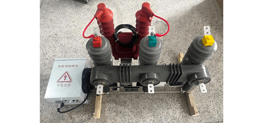
Ang mga low-voltage pole-mounted circuit breakers usa ka kritikal nga protective ug control devices sa mga power systems, diin ang disenyo ug operasyon direkta nga nakaapekto sa safety ug reliability sa sistema. Ang ilang disenyo kinahanglan komprehensibong masolusyonan ang environmental adaptability, electrical parameter coordination, ug actuator selection aron masiguro ang stable nga operasyon sa iba't ibang kondisyon. Sa panahon sa operasyon, ang pagsunod sa estricto nga safety protocols, regular nga maintenance, ug proper nga paghandle sa exceptional situations mahimong essential aron maprevent ang accidents gikan sa misoperation. Kini nga artikulo sistemadiko nga isulat ang key design principles ug operational standards alang sa low-voltage pole-mounted circuit breakers, naghatag og professional nga guidance alang sa engineering personnel.
1. Design Considerations for Low-Voltage Pole-Mounted Circuit Breakers
Ang disenyo sa low-voltage pole-mounted circuit breakers kinahanglan matabangan sa harsh outdoor environments samtang naghahatag og protection ug control requirements.
1.1 Environmental Adaptability
Bilang outdoor-installed equipment, ang mga breakers kinahanglan molambo sa temperature fluctuations, humidity, salt fog corrosion, ug mechanical vibration. Sumala sa GB/T 2423.17, sila kinahanglan dawaton ang 72-hour neutral salt spray test (Grade 5), suitable sa coastal o industrial areas, uban Pollution Degree 3 aron matubagon ang conductive pollution o condensation. Para sa high altitudes (>2000m), ang insulation ug temperature rise parameters kinahanglan i-adjust sumala sa GB/T 20645-2021 (temperature rise limit decreases by 1% per 100m increase; current rating reduction required above 4000m).
Para sa low temperatures, ang operasyon sa -40°C ug storage sa -55°C kinahanglan masigurado, uban reliable nga actuator performance. Ang UV resistance nanginahanglan surface coatings sama sa polyamide paint (contact angle >90°) o PVDF (UV aging resistance ≥ Grade 8). Ang enclosure sealing kinahanglan maipasabot sa IP54/55 standards aron maprevent ang insulation degradation.
1.2 Electrical Parameter Coordination
Ang accurate short-circuit current calculation ug proper parameter selection usa ka crucial. Ang short-circuit currents kinahanglan icompute gamit ang absolute method, considerando ang three-phase, two-phase, ug single-phase ground fault currents. Ang initial three-phase short-circuit current icompute as:

diin Un usa ka nominal line voltage, ug Rk, Xk mao ang total resistance ug reactance sa short-circuit loop. Ang breaker’s rated short-circuit breaking capacity (Ics) wala dapat mubo sa maximum three-phase short-circuit current. Ang sensitivity verification nanginahanglan ang minimum short-circuit current sa line end mao ang at least 1.3 times the instantaneous or short-time overcurrent trip setting: Imin≥1.3Iset3.
Para sa overload protection, ang long-time trip setting Iset1 nanginahanglan satisfy Iz≥Iset1≥Ic, diin Iz usa ka conductor’s continuous current-carrying capacity ug Ic mao ang calculated load current. Para sa short-circuit protection, ang instantaneous trip setting Iset3 wala dapat mubo sa 1.2 times the full starting current of the largest motor (e.g., 20–35 times rated current for squirrel-cage motors), samantalang ang short-time setting Iset2 wala dapat magbutang sa transient load peaks, typical set at 1.2 times (maximum motor starting current + other load currents).

1.3 Actuator Selection
Ang spring-operated mechanisms common nga gigamit, requiring reliability, anti-jump, free-tripping, ug buffering functions. Timing parameters: frame breakers—closing ≤0.2s, opening ≤0.1s; molded-case breakers—mechanical life ≥10,000 operations (frame breakers ≥20,000). Ang actuator kinahanglan include energy storage detection ug interlocking aron masiguro ang safe operation. Ang dynamic characteristics nanginahanglan optimized contact speed ug displacement control (e.g., staged control for vacuum breakers to minimize contact bounce). Ang output characteristics kinahanglan match the breaker aron masiguro ang closure under short-circuit conditions. Sa cold regions, ang capacitor ESR increases at -40°C, prolonging closing time; variable-temperature testing essential.
2. Protection Function Design and Setting Selection
2.1 Overload Protection
Typically implemented via thermal-magnetic or electronic trip units. Thermal-magnetic units use bimetallic strips with inverse-time characteristics (trip time inversely proportional to the square of overload current). Electronic units offer precise control, with long-time trip settings Ir ranging from 0.4 to 1 times the rated current In. Settings must satisfy In≥Ic and In≤Iz. Sensitivity: Sp=Ikmin/Iop≥1.3, where Ikmin is the minimum single-phase short-circuit current at the line end. For critical loads, overload protection may trigger alarms instead of tripping.
2.2 Short-Circuit Protection
Includes short-time and instantaneous protection. Short-time protection ensures selectivity: Iset2≥1.2 (max motor starting current + other loads), with time delays (0.1–0.4s) coordinated with upstream breakers (≥0.1–0.2s time difference). Instantaneous protection targets severe faults: Iset3≥1.2 full motor starting current (e.g., 12–18 times In for motors). For distribution feeders, electronic trip units with delayed instantaneous protection are preferred. Selectivity: upstream short-time setting ≥1.3 × downstream instantaneous setting, with ≥0.1–0.2s time delay difference.
2.3 Undervoltage Protection
Prevents equipment damage from voltage sags. Trip range: 35%–70% of rated voltage. Instantaneous types trip immediately but may cause nuisance tripping; delayed types (0–5s) ignore transient fluctuations, suitable for industrial use. The undervoltage trip unit’s rated voltage must match the line voltage, and its function must not interfere with other protections. Delayed types (0.2–3s) are recommended for industrial applications.
3. Selectivity Coordination and Cascading Protection
3.1 Selectivity Zones
Zone 1 (Isc < downstream Icu): Achieved via current and time grading (e.g., upstream Iset3≥1.2 downstream Iset3, time delay ≥ downstream + 0.1s).
Zone 2 (downstream Icu < Isc < upstream Icu): Relies on current-limiting characteristics or manufacturer data. Selectivity limit Is may be less than downstream Icu (partial selectivity).
Zone 3 (Isc > upstream Icu): Requires testing; upstream contacts may momentarily open (≤30ms) without tripping, provided no welding occurs.
3.2 Cascading Protection
Leverages upstream breaker current-limiting to allow use of lower-breaking-capacity downstream breakers, reducing cost. Requires matching instantaneous settings and avoiding critical loads on cascaded circuits. Energy-based selectivity (e.g., in A-type breakers) can enhance selectivity limits, but verification via manufacturer data is essential.
3.3 Selectivity Methods
Current Selectivity: Upstream instantaneous setting ≥1.3 × downstream.
Time Selectivity: Upstream short-time delay ≥ downstream + 0.1–0.2s.
Energy Selectivity: Based on contact system energy requirements.
Logic Selectivity: Downstream fault detection sends a lockout signal to upstream, enabling fast downstream tripping while upstream remains closed—ensuring "stable, accurate, fast" protection.