Analysis of Interlocking Protection Circuit for Furnace Transformer

Dyson
08/07/2025

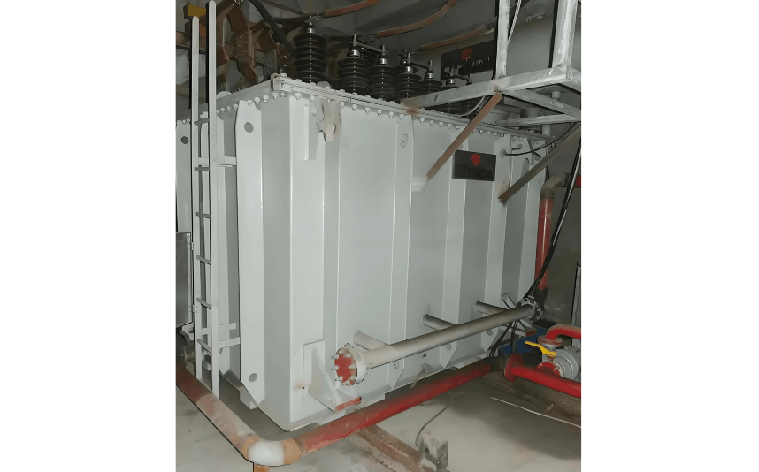
Currently, the company operates two electric arc furnace (EAF) transformers. The secondary voltage ranges from 121 V to 260 V, with a rated current of 504 A / 12,213 A. The high-voltage side has a total of eight tap positions, utilizing motor-driven off-circuit voltage regulation. The equipment is equipped with a reactor of corresponding capacity, connected in series to designated taps on the high-voltage side. These transformers have been in operation for over 20 years. Throughout this period, to meet the evolving demands of the steelmaking process, several technical upgrades have been implemented on the electrode control system and transformer protection system, aiming to ensure safe and stable equipment operation. However, achieving this goal critically depends on the completeness and reliability of the interlocking circuit between the secondary protection circuit of the EAF transformer and the arc furnace's electrode control system. In recent years, several incidents of high-voltage tap changer burnout have occurred, raising concerns about the reliability of the associated interlocking circuits.

1 Accident Phenomenon

Core inspections of the transformers revealed that all failures involved burnout of the high-voltage side tap changer. In each incident, the secondary protection on the high-voltage side operated reliably. The instantaneous overcurrent protection setting for the high-voltage switch was 6,000 A on the primary side, meaning the protection would only activate if the short-circuit current through the tap changer exceeded 6,000 A instantaneously. However, the rated current of the tap changer itself is only 630 A.

2 Root Cause Analysis

The steelmaking process consists of three stages: melting, oxidation, and reduction. During the melting stage, the three-phase load fluctuates dramatically, generating large inrush currents that are often unbalanced. Even during the refining stage, continuous changes in the arc discharge path and arc gap ionization lead to constantly unbalanced load currents, resulting in zero-sequence components. When these zero-sequence components are reflected onto the star-connected high-voltage winding, they cause neutral point voltage displacement.

Based on the observed failure phenomena, various contributing conditions were analyzed. Detailed studies were conducted on the electrical circuits of the arc furnace electrode control system, the interlock relationship between the high-voltage secondary protection circuit, and the positions of the tap changer during gear shifting. Field tests were repeatedly performed to simulate whether the conditions leading to failure could occur during steelmaking. Ultimately, the following deficiencies in the interlocking protection circuit on the high-voltage side of the EAF transformer were identified. During steelmaking, the occurrence of any one of the following conditions could lead to tap changer burnout:

  • Performing tap changing after high-voltage power shutdown. During the tap changing process using the tap changer controller, the digital display may indicate completion, but the tap changer has not fully reached its position (i.e., the contact area between moving and stationary contacts has not reached the required capacity). If high-voltage power is restored under these conditions, it can lead to phase-to-phase short circuits and subsequent burnout of the tap changer during steelmaking.
  • Tap changing under voltage, i.e., directly changing the tap position of the tap changer while the arc furnace is operating.
  • Energizing under load, i.e., restoring high-voltage power while the three-phase electrodes of the arc furnace are still in contact with molten steel.

3 Improvement Measures

Compared to conventional power transformers, EAF transformers have the following characteristics: higher overload capacity, greater mechanical strength, larger short-circuit impedance, multiple secondary voltage levels, higher transformation ratios, low secondary voltage (tens to hundreds of volts), and high secondary current (thousands to tens of thousands of amperes). Current control in the arc furnace is achieved by changing the tap connections on the high-voltage side of the transformer and adjusting the electrode positions.

During steelmaking, according to process requirements and the operational nature of the EAF transformer, the two high-voltage switchgear units installed at the furnace front operate dozens or even hundreds of times per day. This places rigorous demands on the performance of vacuum switches and the reliability of protective operations. Therefore, the design incorporates a "one-in-use, one-on-standby" configuration, controlled from the furnace front operator station. Power is supplied via high-voltage power cables from the company's 66 kV central substation.

Given the deficiencies in the interlocking protection control circuit, it is essential to prevent the conditions that lead to tap changer burnout during steelmaking operations. Through analysis of the interlocking circuit, simulation testing, structural study of the tap changer, and understanding of the steelmaking process, the following corrective measures were developed:

  • Prohibit high-voltage energization until tap changing is fully completed;
  • Prohibit tap changing while the high-voltage side is energized;
  • Prohibit energizing the transformer under load.

4 Conclusion

By implementing the above solutions to address the deficiencies in the EAF transformer's interlocking protection control circuit, the reliability of the interlock system has been significantly enhanced. This effectively prevents operational errors by personnel from causing equipment damage, ensuring the safe, stable, and reliable operation of the EAF transformers. It also guarantees the successful completion of the company's steelmaking production tasks and substantially reduces equipment maintenance costs.

Dyson

Focused on the design of electrical equipment, proficient in electrical principles and relevant specifications, and skilled in using design software. From intelligent substations to various types of electrical equipment, I am adept at optimizing design solutions, integrating new technologies. With practical experience and collaborative management capabilities, I deliver outstanding electrical design achievements.

Common Faults and Diagnostic Technologies of Oil-immersed Distribution Transformers
1.Common Faults and Diagnostic Measures1.1 Transformer Oil Leakage1.1.1 Oil Leakage from Tank Weld SeamsFor oil leakage at flat joints, direct welding is applicable. For leakage at corners or joints reinforced with stiffeners, the exact leakage point is often difficult to locate, and re-leakage may occur after welding due to internal stress. For such cases, repair welding with an added iron plate is recommended: for two-surface joints, the iron plate can be cut into a spindle shape for welding;
Vziman
08/07/2025
Analysis of the Causes of Light Gas Generation in Electric Furnace Transformers and Improvements
A 25 MVA electric arc furnace transformer at a certain company is an equipment imported from the former Soviet Union. It consists of three single-phase transformers, each rated at 8.333 MVA, with a connection group of D,d0. The primary voltage is 10 kV, and the secondary voltage ranges from 140 to 230.4 V. The tap-changing method is on-load tap changing with 21 steps (steps 11, 12, and 13 are combined as one step, totaling 23 positions). Each phase can be regulated independently, allowing separa
Felix Spark
08/06/2025
Why does inrush current occur in arc furnace transformers?
Magnetizing inrush current in electric arc furnace transformers is a problem that troubles many electrical engineers. So, why does magnetizing inrush current occur in arc furnace transformers? First, let's understand what magnetizing inrush current is.Magnetizing inrush current refers to the transient current generated in the secondary winding of an arc furnace transformer due to core saturation, increased magnetic field strength, and other factors. This phenomenon is very common during the oper
Echo
08/06/2025
Why do arc furnace transformers and inrush currents cause voltage sags?
An electric arc furnace is a device that melts metal using the high temperature generated by an electric arc. It converts electrical energy into thermal energy through a transformer, then transfers the heat via the arc to the furnace charge, causing it to melt. When the arc furnace starts operating, the transformer load increases suddenly, leading to a drop in grid voltage. Additionally, due to the operational characteristics of the arc furnace, the load continues to rise over a period of time,
Leon
08/06/2025
Inquiry
Download
IEE-Business is dedicated to serving the personnel in the global power industry.
Join IEE-Business, not only can you discover power equipment and power knowledge, but also canhnd like - minded friends!