Rakîtoran dijî ye ku bêyînên reaktîvî yên wergerîn da, û rakîtoran bi kontrol magnetîk ji bo dîtina zanistî. Gridê pîçaz jî yên tradîsyonel bi teknolojîya pirastî sererast kirin, amna û behezdarîyan berdibandin, vebijarkirina rakîtoran bi kontrolê digehîne. Ji ber vê yekê, çêkirina noji-rewşên wan dikare were biçav kirin. Ev nivîs, bi taybetmendîyek, li ser rêzikarî û karberdanan wekîn guhertin û bixweberandina gridê pîçaz bibin.
1 Fonksiyon û Rewşê Karberdariyê ya Rakîtoran bi Kontrol
1.1 Fonksiyon
Li gor êndezan, rakîtoran bi kontrol herînên şêtê, faktorê elektrîkî di vir 0.9 de, tergînên hilkerdiyan, haddên dampîng, kapasîtekî şêtê, û stabîlîtekî voltajê. Li gor karberan, wan: ① Voltajê stabîl bikin, cihazan sija transformeran parast bikin, û dema xebatê zêde bikin. ② Harmonîkên hilkerdin, herînên hilkerdin, û behezîyetîn. ③ Terzînan voltajê, kalîtey elektrîkê zêde bikin. ④ Herînên reaktîvî yên karberan bi hewceyên mezin, mablagên elektrîkê kêm bikin. ⑤ Bixweberandina kapasîtekî bi mablagên kêm bi kompensasyona dinamîk.
1.2 Rewşê Karberdariyê
Rakîtoran bi kontrol bi destûrî li ser sisteman elektrîkî hatine karberd kirin, wisa li ser êndezan elektrîkî, êndezan endustriyî, xebata elektrîkî nû û sahmanan din. Bi zêdetirina hewceyên elektrîkî û nirxandina gridê pîçaz, hewceyê bazarî yên rakîtoran bi kontrol da dibishtin.
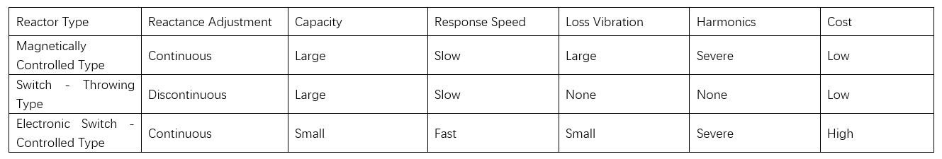
Rakîtoran sê rewş hatine: kontrol magnetîk, kontrol pergalî, û kontrol elektronîk. Rakîtoran bi kontrol magnetîk piştguhînên dinamîk, kapasîtekî mezin, û mablagên kêm an, lê tepada yekbûyî, herînên hilkerd û harmonîkên mezin. Rakîtoran bi kontrol pergalî herînên hilkerd û harmonîkên hilkerdin, lê piştguhînên nederbar, li ser karberdan kêm bingehat. Rakîtoran bi kontrol elektronîk piştguhînên dinamîk bi tepada yekbûyî, lê herînên hilkerd û mablagên mezin. Rakîtoran bi kontrol magnetîk bingehatir ne. Ji bo peyda kirina gridê pîçaz, girîng e ku bahan û strukturan veqetandin û dizaynên nû bike.
2 Dizaynê Strukturî ya Rakîtoran bi Kontrol li Ser Gridê Pîçaz
Gridê pîçaz, an Grid 2.0, li ser rêzikarên pêş û derve sererastdir. Bi cihazên nû, teknolojî û metoda, amna û behezdarî, ramî û ekonomîyê, û bixweberandina kalîteyê elektrîkî li ser hewceyên karberan. Rakîtoran bi kontrol niha bingehatîn ji bo bixweberandina gridê pîçaz. Di navbera, dizaynê strukturî wan li ser bahan magnetîk nanokompozit hatine.
2.1 Hilbijartina Bahan Magnetîk
Bahan magnetîk nanokompozit ji fazeyên magnetîk hard û soft nanokristalîn têkildar e. Tîrînên wan di navber û têkildar de, têkilek exchange bi destûrî di têkilde. Miyanî, li ser penîparan fazeyan, momentan magnetîk fîlan reorient bikin, remanansê zêde bikin. Li ser rakîtoran bi kontrol: DC bi têkilde têkilî, bahan magnetîk; AC fîlan demagnetize bikin.
Bi rêzikarê melt rapid quenching, malbatê tempering bike û strukturê mikrokanîk tune bike. Vê tîrînên zêde bikin û coercivity kêm bikin, li ser hewceyên tune bike.
2.2 Dizaynê Cilî Strukturî
Strukturê rakîtoran bi kontrol têkildar e tiştên, birînên fer, clamp, working windings, control windings, û bahan magnetîk nanokompozit. Sütun excitation, ji bahan magnetîk û pelên silîkî, li navendî ye. Working windings li girtî, bi layerên derveyan wekî rûpelên magnetîk serpil. Control winding li ser bahan magnetîk biskînin.
Serniya: Di navbera operasyonê normal ê (ji bo hilkerdina harmonîk û tune reaktîv), rakîtor voltage, current, û power reaktîv detect bikin. Agahîyên wan duhet bigere ser sistemê kontrolî li ser evalûasyonê statusê grid. Ji bo hilkerdina harmonîk û tune reaktîv, sistemê kontrolî currentê winding tune bike. Bahan magnetîk reaktansê bi magnetizasyon tune bikin. Ji ber vê yekê, parametreyan bi spesifikasyonan dizayn tune bikin, currentê winding tune bike û bahan magnetîk bi remanansê zero tune bikin.
Li ser circuitê dizayn, herînên leakage fluxê primary û secondary negire, eme:
Yekê ku: E1 represent the induced electromotive force of W1; E2 represent the induced electromotive force of W2; E3 represent the induced electromotive force of W3. Further, by using a T - type circuit to equate the two - port network of the controllable reactor, we can obtain:

Let Ik = β Ig, and the inductance value of the working port is:

The reactance control coefficient is α, and Ik = αIg. The relationship between the reactance of the working port and α is:

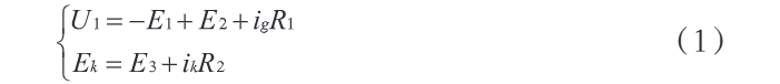
By connecting the working port in parallel with the power grid and treating U1 as a constant, the following system of equations can be obtained:
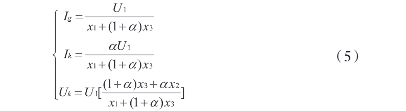
Where: Ig and Ik denote the effective values of the currents at the two ports; Uk represents the effective value of the voltage at the control port. Solving the system of equations in Formula (5) allows us to obtain the operating performance indicators of the controllable reactor.
2.3 Control System Design
Sistemê kontrol têkildar e main circuit (tune remanansê bahan magnetîk) û detection-control subsystem (monitoring electrical parameters), li ser hev tune management goals. Ji ber vê yekê, currentê main circuit bi tune magnetize/demagnetize materials, û subsystem loads monitor bike bi tune optimal, li ser stabîlîtekî grid. Reaktans changes stem from core magnetic state shifts. Controllable rectification enables millisecond-level AC output, meeting rapid magnetic state conversion needs. The system issues commands for the reactor to suppress harmonics and regulate reactive power, maintaining grid stability.
Operation process: 1) Detect grid status, collect parameters, and assess stability. 2) When voltage fluctuations/harmonics occur, the reactor's control system issues commands. 3) The main circuit outputs adjustable inductance; materials magnetize, altering remanence/core state and thus reactor inductance. 4) Post-adjustment, reverse-adjust inductance to demagnetize materials and reset the reactor. Matlab simulations verified system accuracy: 15 A magnetizing current and 220 V demagnetizing voltage with stable waveforms, meeting magnetization/demagnetization requirements.
3 Experimental Analysis of Reactance Adjustment Effect
To verify the reactor's reactance adjustment performance, a prototype and supporting control system were built per design and simulations. Experiments analyzed inductance distribution characteristics and evaluated grid power quality changes.
3.1 Stability of the Controllable Reactor
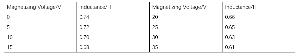
In the experiment, data were collected to plot the volt - ampere characteristic curve and operating current curve of the controllable reactor. The results show that: ① As the voltage value increases, the current of the working winding rises, and the two show a linear relationship, indicating that under different magnetizing voltages, the inductance value stays within a relatively constant range. ② When the magnetizing voltage is 0–35 V, the inductance decreases from 0.74 H to 0.61 H, and the inductance output is stable, meeting the requirement for smooth adjustment. The change of inductance with the magnetizing voltage is shown in Table 2.
In this study, the change in the inductance value of the controllable reactor is achieved through the magnetization and demagnetization of magnetic materials, which in turn depends on the alternating current and direct current passed into the control winding. This operation will also bring disturbances to the working winding. Therefore, it is necessary to further analyze its working transient process. To this end, a mixed-domain oscilloscope was used to collect the current waveforms of the magnetic materials during magnetization and demagnetization. The results show that the reactor responds quickly, and the current waveform is in a stable state after magnetization is completed.
3.2 Measured Results of Inductance Value
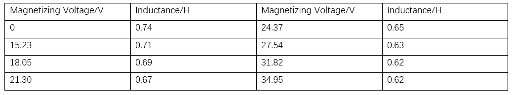
During the actual operation of the controllable reactor, the inductance values obtained by applying different magnetizing voltages are shown in Table 3. The analysis reveals that: ① The inductance value of the reactor changes approximately linearly with the variation of the remanence of the magnetic material. This means that even a slight change in the DC voltage can effectively adjust the inductance value of the reactor. ② By precisely regulating the magnetic state of the magnetic material, the controllable reactor can flexibly change its inductance value, thereby achieving effective compensation of the reactive power in the power line.
3.3 Changes in Power Grid Power Quality
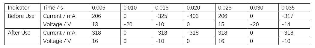
In the power system, the current and voltage changes on the high - voltage side of the transformer before and after using the controllable reactor were recorded, and the harmonic characteristics were observed. The results are shown in Table 4. The analysis shows that: ① Before using the controllable reactor, the current and voltage changes on the high - voltage side were complex, and their waveforms had no regular features; after using the controllable reactor, the current and voltage waveforms on the high - voltage side were improved and had obvious regular features. ② After using the controllable reactor, the harmonic content decreased, the active power increased, and the power quality was significantly improved.
4 Conclusion
In conclusion, reactors play a crucial role in power systems, stabilizing voltage, suppressing harmonics, damping oscillations, and boosting power factor. Among existing types, magnetically controlled reactors, with continuous reactance adjustment, large capacity, and low cost, are widely used in power systems. To address issues like slow response and high loss vibration of magnetically controlled reactors, this study designs a controllable reactor using nanocomposite magnetic materials.
Experimental conclusions: ① The reactor responds rapidly, with stable current waveforms after magnetization. ② Even small DC voltage changes can effectively adjust inductance. By precisely regulating the magnetic state of materials, the reactor flexibly changes inductance to compensate reactive power in power lines. ③ After application, high - voltage side current/voltage waveforms and power quality improve significantly, suitable for smart grid promotion. In the future, with new materials, technologies, and processes, controllable reactors will be optimized to better meet smart grid needs and ensure stable grid operation.