Reactors na da muhimmanci wajen kammal girmama da ba ta dacewa a cikin gwamnati, musamman reactors da ake kontrola da aiki. Grid mai zurfi, wanda yake zama babban abu a cikin fannonin tattalin arziki, yana haifar da dalilin amincewa da ingantaccen hankali, wanda ke nuna bukatar reactors da za su iya kontrola. Saboda haka, ya kamata bayanai game da wannan abu. Wannan takarda, tun daga tushen rayuwa, yana bincike tsarin kudin da amfani da shi don kula'ar da zuwa waɗannan abubuwa.
1 Funtunan da Amfani da Reactors Da Za Su Iya Kontrola
1.1 Funtunan
Don grids, reactors da za su iya kontrola suna kawo karfi, suna kawo power factor a 0.9, suna haifar da oskilashin, suna fiye limits da ke haifar da damping, suna kawo capacity da za su ina kawo, da kuma suna kawo voltage stability. Don masu amfani, suna: ① Kula'ar da voltage, kawo kyakkyawan wasu wurare masu aiki kamar transformers, da kuma kawo tsari. ② Cire harmonics, kawo karfi, da kuma kawo dalili. ③ Haifar da voltage flicker, kula'ar da quality da energy. ④ Kudin reactive losses don masu amfani da kyakkyawan talabu, kawo karfi da cost. ⑤ Bayyana karfi da za su iya kawo via dynamic compensation.
1.2 Amfani Da Tsarin
Reactors da za su iya kontrola suna amfani a matsayin gwamnatin kwamfuta, utilities masu aiki, new energy power generation da sauransu. Daga bakin rarrabe talabu da ziyarta da cikin tattalin gwamnati, bukatar da reactors da za su iya kontrola yana ci gaba.
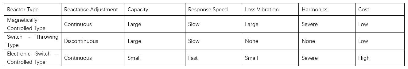
Reactors ana nan kamar haka: magnetic control, switch-throwing, da electronic-switch control. Magnetic control reactors suna bayyana adjustment da lafiya, capacity da kyau, da kuma karfi, amma suna da response da lafiya, karfi da vibration, da kuma harmonics. Switch-throwing ones suna haifar da vibration/harmonics amma suna da adjustment da ba da lafiya, wanda ke haifar da amfani. Electronic-switch types suna bayyana adjustment da lafiya da response da lafiya amma suna da harmonics da karfi. Magnetic control reactors suna da al'amuran da ke da su. Don kuwa da grid mai zurfi, ya kamata lissafin materials/structure da designs masu zamani.
2 Tsarin Kudin Reactors Da Za Su Iya Kontrola A Cikin Grids Mai Zurfi
Grid mai zurfi, ko Grid 2.0, take da networks da ke amfani da communication da lafiya. Yana amfani da equipment, tech, da methods masu zamani don kawo grid safety, efficiency, environmental-friendliness, da economy, da kuma kula'ar da talabu masu amfani da quality da energy. Reactors da za su iya kontrola suna da muhimmanci wajen kammal grid mai zurfi. Hakan ne tsarin kudin based on nanocomposite magnetic materials.
2.1 Zabbar Materials Masu Magnetic
Nanocomposite magnetic materials suna nan kamar hard da soft magnetic phases. Grains suna interact, suna bayyana coupled exchange effect under current. Microscopically, at phase interfaces, magnetic moments suna reorient fields during interaction, suna kawo remanence. In controllable reactors: DC applied to windings creates an excitation field, magnetizing the material; AC forms an attenuating field, demagnetizing it.
Prepared via melt rapid quenching, the material undergoes tempering to adjust its microstructure. This enlarges grains and reduces coercivity, meeting adjustment needs.
2.2 Tsarin Kudin Duka
The controllable reactor's structure comprises tie rods, an iron core, clamps, working windings, control windings, and nanocomposite magnetic materials. The excitation column, made of magnetic materials and silicon steel sheets, sits at the center. Working windings flank it, with their outermost layers as main magnetic circuits. The control winding wraps around the magnetic materials.
Principle: During normal grid operation (no harmonic suppression/reactive regulation needed), the reactor detects voltage, current, and reactive power. These data go to the control system for grid status evaluation. For harmonic suppression or reactive regulation, the control system adjusts winding current. Magnetic materials change reactance via magnetization. Once parameters meet design specs, winding current is adjusted again to demagnetize the materials back to zero remanence.
Per the design circuit, ignoring primary- and secondary-side leakage fluxes, we get:
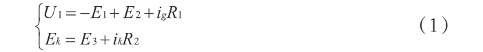
Where: E1 represents the induced electromotive force of W1; E2 represents the induced electromotive force of W2; E3 represents the induced electromotive force of W3. Further, by using a T-type circuit to equate the two-port network of the controllable reactor, we can obtain:

Let Ik = β Ig, and the inductance value of the working port is:

The reactance control coefficient is α, and Ik = αIg. The relationship between the reactance of the working port and α is:

By connecting the working port in parallel with the power grid and treating U1 as a constant, the following system of equations can be obtained:
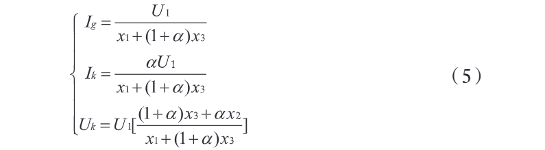
Where: Ig and Ik denote the effective values of the currents at the two ports; Uk represents the effective value of the voltage at the control port. Solving the system of equations in Formula (5) allows us to obtain the operating performance indicators of the controllable reactor.
2.3 Tsarin Control System
The control system comprises a main circuit (adjusting magnetic material remanence) and a detection-control subsystem (monitoring electrical parameters), working together to achieve management goals. When grid operation requires reactance adjustment, the main circuit applies currents to magnetize/demagnetize materials, while the subsystem monitors loads to keep parameters optimal, ensuring grid stability. Reactance changes stem from core magnetic state shifts. Controllable rectification enables millisecond-level AC output, meeting rapid magnetic state conversion needs. The system issues commands for the reactor to suppress harmonics and regulate reactive power, maintaining grid stability.
Operation process: 1) Detect grid status, collect parameters, and assess stability. 2) When voltage fluctuations/harmonics occur, the reactor's control system issues commands. 3) The main circuit outputs adjustable inductance; materials magnetize, altering remanence/core state and thus reactor inductance. 4) Post-adjustment, reverse-adjust inductance to demagnetize materials and reset the reactor. Matlab simulations verified system accuracy: 15 A magnetizing current and 220 V demagnetizing voltage with stable waveforms, meeting magnetization/demagnetization requirements.
3 Experimental Analysis of Reactance Adjustment Effect
To verify the reactor's reactance adjustment performance, a prototype and supporting control system were built per design and simulations. Experiments analyzed inductance distribution characteristics and evaluated grid power quality changes.
3.1 Stability of the Controllable Reactor
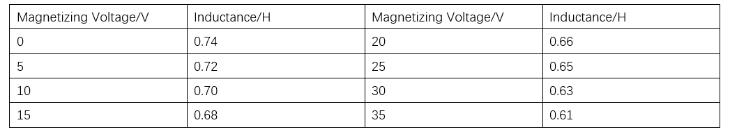
In the experiment, data were collected to plot the volt-ampere characteristic curve and operating current curve of the controllable reactor. The results show that: ① As the voltage value increases, the current of the working winding rises, and the two show a linear relationship, indicating that under different magnetizing voltages, the inductance value stays within a relatively constant range. ② When the magnetizing voltage is 0–35 V, the inductance decreases from 0.74 H to 0.61 H, and the inductance output is stable, meeting the requirement for smooth adjustment. The change of inductance with the magnetizing voltage is shown in Table 2.
In this study, the change in the inductance value of the controllable reactor is achieved through the magnetization and demagnetization of magnetic materials, which in turn depends on the alternating current and direct current passed into the control winding. This operation will also bring disturbances to the working winding. Therefore, it is necessary to further analyze its working transient process. To this end, a mixed-domain oscilloscope was used to collect the current waveforms of the magnetic materials during magnetization and demagnetization. The results show that the reactor responds quickly, and the current waveform is in a stable state after magnetization is completed.
3.2 Measured Results of Inductance Value
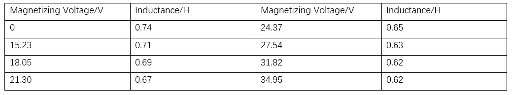
During the actual operation of the controllable reactor, the inductance values obtained by applying different magnetizing voltages are shown in Table 3. The analysis reveals that: ① The inductance value of the reactor changes approximately linearly with the variation of the remanence of the magnetic material. This means that even a slight change in the DC voltage can effectively adjust the inductance value of the reactor. ② By precisely regulating the magnetic state of the magnetic material, the controllable reactor can flexibly change its inductance value, thereby achieving effective compensation of the reactive power in the power line.
3.3 Changes in Power Grid Power Quality
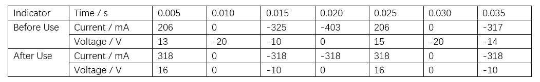
In the power system, the current and voltage changes on the high-voltage side of the transformer before and after using the controllable reactor were recorded, and the harmonic characteristics were observed. The results are shown in Table 4. The analysis shows that: ① Before using the controllable reactor, the current and voltage changes on the high-voltage side were complex, and their waveforms had no regular features; after using the controllable reactor, the current and voltage waveforms on the high-voltage side were improved and had obvious regular features. ② After using the controllable reactor, the harmonic content decreased, the active power increased, and the power quality was significantly improved.
4 Conclusion
In conclusion, reactors play a crucial role in power systems, stabilizing voltage, suppressing harmonics, damping oscillations, and boosting power factor. Among existing types, magnetically controlled reactors, with continuous reactance adjustment, large capacity, and low cost, are widely used in power systems. To address issues like slow response and high loss vibration of magnetically controlled reactors, this study designs a controllable reactor using nanocomposite magnetic materials.
Experimental conclusions: ① The reactor responds rapidly, with stable current waveforms after magnetization. ② Even small DC voltage changes can effectively adjust inductance. By precisely regulating the magnetic state of materials, the reactor flexibly changes inductance to compensate reactive power in power lines. ③ After application, high-voltage side current/voltage waveforms and power quality improve significantly, suitable for smart grid promotion. In the future, with new materials, technologies, and processes, controllable reactors will be optimized to better meet smart grid needs and ensure stable grid operation.