• Product
  • Suppliers
  • Manufacturers
  • Solutions
  • Free tools
  • Knowledges
  • Experts
  • Communities
Search


What is a Shunt Capacitor?

Encyclopedia
Encyclopedia
Field: Encyclopedia
0
China


What is a Shunt Capacitor?


Shunt Capacitor Definition


A shunt capacitor is defined as a device used to improve power factor by providing capacitive reactance to counteract inductive reactance in electrical power systems.


Power Factor Compensation


Shunt capacitors help improve the power factor, which reduces line losses and improves voltage regulation in power systems.
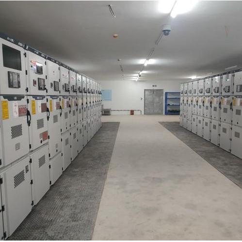

Capacitor Bank


The capacitor reactance is generally applied to the system by using static capacitor in shut or series with system. Instead of using a single unit of capacitor per phase of the system, it is quite effective to use a bank of capacitor units, in the view of maintenance and erection. This group or bank of capacitor units is known as capacitor bank.


There are mainly two categories of capacitor bank according to their connection arrangements.


  • Shunt capacitor.

  • Series capacitor.


The Shunt capacitor is very commonly used.


Connection of Shunt Capacitor Bank


The capacitor bank can be connected to the system either in delta or in star. In star connection, the neutral point may be grounded or not depending upon protection scheme for capacitor bank adopted. In some cases the capacitor bank is formed by double star formation.Generally large capacitor bank in electrical substation is connected in star.


The grounded star connected bank has some specific advantages, such as,


  • Reduced recovery voltage on circuit breaker for normal repetitive capacitor switching delay.


  • Better surge protection.


  • Comparatively reduced over voltage phenomenon.


  • Lesser cost of installation.


In a solidly grounded system, the voltage of all three phases of a capacitor bank remains fixed, even during two-phase operation.


Location Considerations


Ideally, a capacitor bank should be placed near reactive loads to minimize reactive power transmission across the network. When a capacitor and load are connected together, they disconnect simultaneously, preventing overcompensation. However, it’s not practical or economical to connect a capacitor to each individual load due to varying load sizes and availability of capacitors. Additionally, not all loads are connected continuously, so the capacitors may not be fully utilized.


Hence, capacitor, is not installed at small load but for medium and large loads, capacitor bank can be installed at consumer own premises. Although the inductive loads of medium and large bulk consumers are compensated, but still there would be considerable amount of VAR demand originated from different uncompensated small loads connected to the system. In addition to that, inductance of line and transformer also contribute VAR to the system. On viewing of these difficulties, instead of connecting capacitor to each load, large capacitor bank is installed at main distribution sub-station or secondary grid sub-station.


Give a tip and encourage the author!
Recommended
MVDC: Future of Efficient, Sustainable Power Grids
The Global Energy Landscape Is Undergoing a Fundamental Transformation toward a "fully electrified society," characterized by widespread carbon-neutral energy and the electrification of industry, transportation, and residential loads.In today’s context of high copper prices, critical mineral conflicts, and congested AC power grids, Medium-Voltage Direct Current (MVDC) systems can overcome many limitations of traditional AC networks. MVDC significantly enhances transmission capacity and efficienc
Edwiin
10/21/2025
Grounding Causes of Cable Lines and the Principles of Incident Handling
Our 220 kV substation is located far from the urban center in a remote area, surrounded primarily by industrial zones such as Lanshan, Hebin, and Tasha Industrial Parks. Major high-load consumers in these zones—including silicon carbide, ferroalloy, and calcium carbide plants—account for approximately 83.87% of our bureau’s total load. The substation operates at voltage levels of 220 kV, 110 kV, and 35 kV.The 35 kV low-voltage side mainly supplies feeders to ferroalloy and silicon carbide plants
Felix Spark
10/21/2025
Overhead Power Lines & Towers: Types, Design & Safety
Besides ultra-high voltage AC substations, what we encounter more frequently are power transmission and distribution lines. Tall towers carry conductors that leap across mountains and seas, stretching into the distance before reaching cities and villages. This is also an interesting topic—today, let's explore transmission lines and their supporting towers.Power Transmission and DistributionFirst, let’s understand how electricity is delivered. The electric power industry primarily consists of fou
Encyclopedia
10/21/2025
Automatic Reclosing Modes: Single, Three-Phase & Composite
General Overview of Automatic Reclosing ModesTypically, automatic reclosing devices are categorized into four modes: single-phase reclosing, three-phase reclosing, composite reclosing, and disabled reclosing. The appropriate mode can be selected based on load requirements and system conditions.1. Single-Phase ReclosingMost 110kV and higher transmission lines employ three-phase single-shot reclosing. According to operational experience, over 70% of short-circuit faults in high-voltage overhead li
Edwiin
10/21/2025
Send inquiry
Download
Get the IEE Business Application
Use the IEE-Business app to find equipment, obtain solutions, connect with experts, and participate in industry collaboration anytime, anywhere—fully supporting the development of your power projects and business.