• Product
  • Suppliers
  • Manufacturers
  • Solutions
  • Free tools
  • Knowledges
  • Experts
  • Communities
Search


Impedance of Transformer

Encyclopedia
Encyclopedia
Field: Encyclopedia
0
China

Leakage Reactance Definition


In a transformer, not all the flux links both the primary and secondary windings. Some flux links with only one winding, called leakage flux. This leakage flux causes self-reactance in the affected winding.


This self-reactance is also known as leakage reactance. When combined with the transformer’s resistance, it forms impedance. This impedance causes voltage drops in both the primary and secondary windings.


Resistance of Transformer


The primary and secondary windings of a electrical power transformer are usually made of copper, which is a good conductor of current but not a superconductor. Superconductors are not practically available. Therefore, these windings have some resistance, known collectively as the transformer’s resistance.


Impedance of Transformer


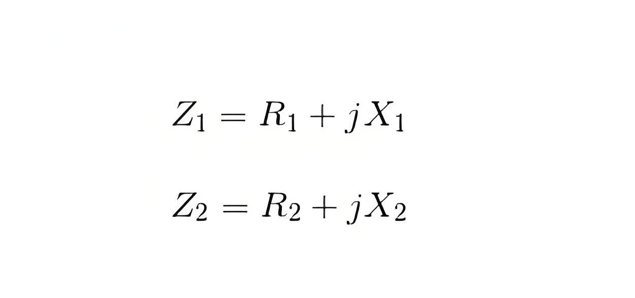
As we said, both primary and secondary windings will have resistance and leakage reactance. These resistance and reactance will be in combination, is nothing but impedance of transformer. If R1 and R2 and X1 and X2 are primary and secondary resistance and leakage reactance of transformer respectively, then Z1 and Z2 impedance of primary and secondary windings are respectively,


0fcb8e893e3907077dd9d360d748db34.jpeg


The Impedance of transformer plays a vital role during parallel operation of transformer


Leakage Flux in Transformer


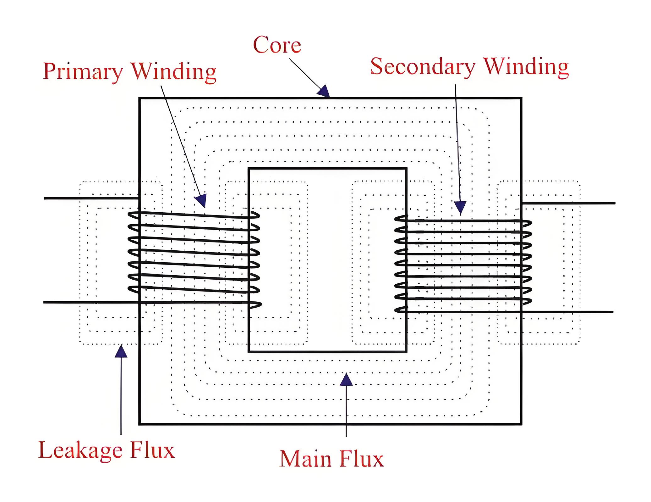
In an ideal transformer, all the flux would link both the primary and secondary windings. However, in reality, not all flux links with both windings. Most flux passes through the core of transformer, but some flux links with only one winding. This is called leakage flux, which passes through the winding insulation and transformer oil instead of the core.


Leakage flux causes leakage reactance in both primary and secondary windings, known as magnetic leakage.


5eca8e676844006960dabbb6691d6ae4.jpeg


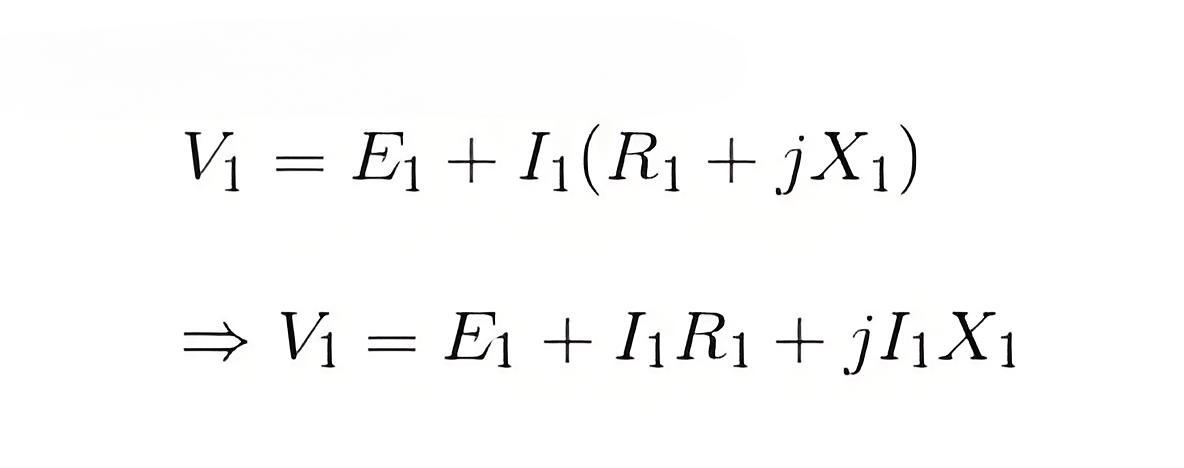
Voltage drops in the windings occur due to impedance of transformer. Impedance is combination of resistance and leakage reactance of transformer. If we apply voltage V1 across primary of transformer, there will be a component I1X1 to balance primary self induced emf due to primary leakage reactance. (Here, X1 is primary leakage reactance). Now if we also consider voltage drop due to primary resistance of transformer, then voltage equation of a transformer can easily be written as,


1b1e15812c808582b64ae2424692eb99.jpeg


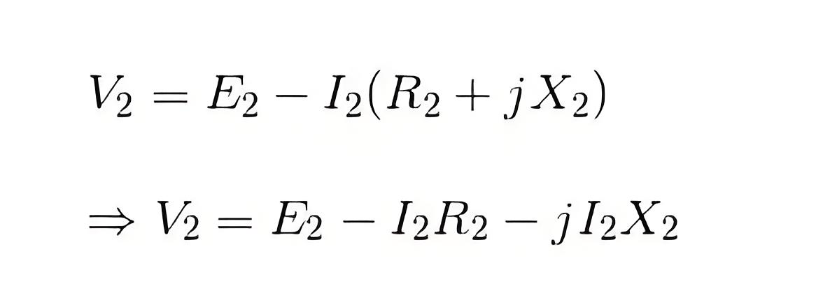
Similarly for secondary leakage reactance, the voltage equation of secondary side is,


cf81a0116f8510e36defe66852bb6ce1.jpeg


Here in the figure above, the primary and secondary windings are shown in separate limbs, and this arrangement could result in a large leakage flux in transformer because there is a big room for leakage. 


Leakage in primary and secondary windings could be eliminated if the windings could be made to occupy the same space. This, of course, is physically impossible but, by placing secondary and primary in a concentric manner can solve the problem to a good extent. 


Give a tip and encourage the author!
Recommended
MVDC: Future of Efficient, Sustainable Power Grids
The Global Energy Landscape Is Undergoing a Fundamental Transformation toward a "fully electrified society," characterized by widespread carbon-neutral energy and the electrification of industry, transportation, and residential loads.In today’s context of high copper prices, critical mineral conflicts, and congested AC power grids, Medium-Voltage Direct Current (MVDC) systems can overcome many limitations of traditional AC networks. MVDC significantly enhances transmission capacity and efficienc
Edwiin
10/21/2025
Grounding Causes of Cable Lines and the Principles of Incident Handling
Our 220 kV substation is located far from the urban center in a remote area, surrounded primarily by industrial zones such as Lanshan, Hebin, and Tasha Industrial Parks. Major high-load consumers in these zones—including silicon carbide, ferroalloy, and calcium carbide plants—account for approximately 83.87% of our bureau’s total load. The substation operates at voltage levels of 220 kV, 110 kV, and 35 kV.The 35 kV low-voltage side mainly supplies feeders to ferroalloy and silicon carbide plants
Felix Spark
10/21/2025
Overhead Power Lines & Towers: Types, Design & Safety
Besides ultra-high voltage AC substations, what we encounter more frequently are power transmission and distribution lines. Tall towers carry conductors that leap across mountains and seas, stretching into the distance before reaching cities and villages. This is also an interesting topic—today, let's explore transmission lines and their supporting towers.Power Transmission and DistributionFirst, let’s understand how electricity is delivered. The electric power industry primarily consists of fou
Encyclopedia
10/21/2025
Automatic Reclosing Modes: Single, Three-Phase & Composite
General Overview of Automatic Reclosing ModesTypically, automatic reclosing devices are categorized into four modes: single-phase reclosing, three-phase reclosing, composite reclosing, and disabled reclosing. The appropriate mode can be selected based on load requirements and system conditions.1. Single-Phase ReclosingMost 110kV and higher transmission lines employ three-phase single-shot reclosing. According to operational experience, over 70% of short-circuit faults in high-voltage overhead li
Edwiin
10/21/2025
Related Products
Send inquiry
Download
Get the IEE Business Application
Use the IEE-Business app to find equipment, obtain solutions, connect with experts, and participate in industry collaboration anytime, anywhere—fully supporting the development of your power projects and business.