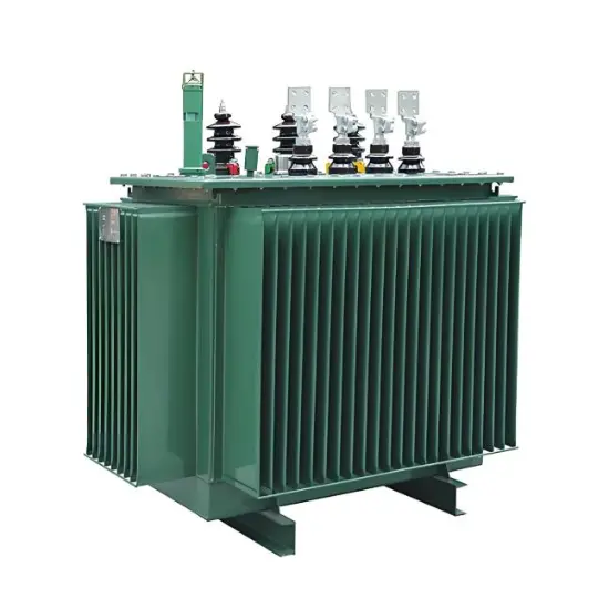
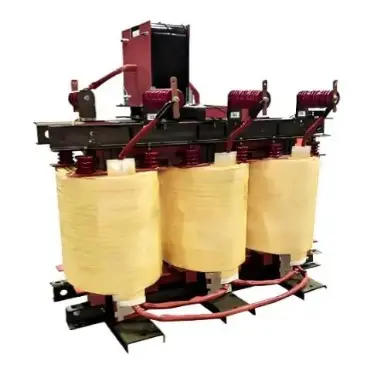
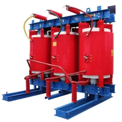
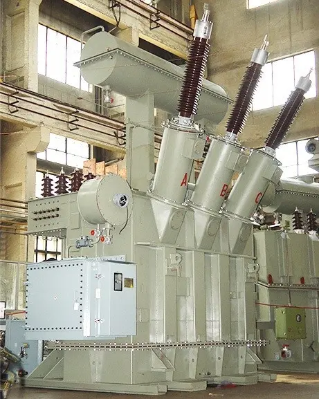
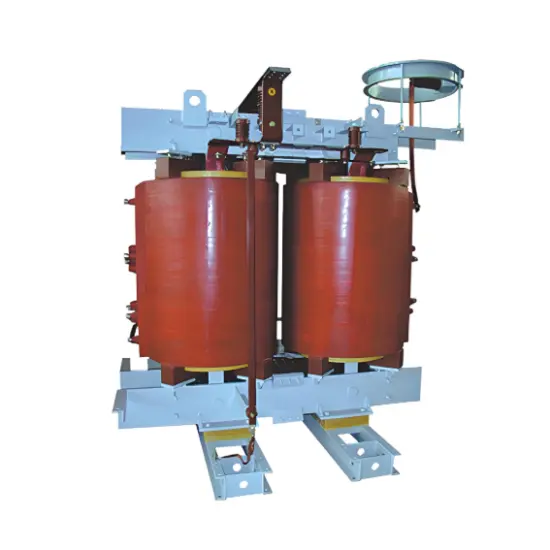
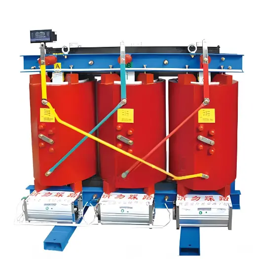
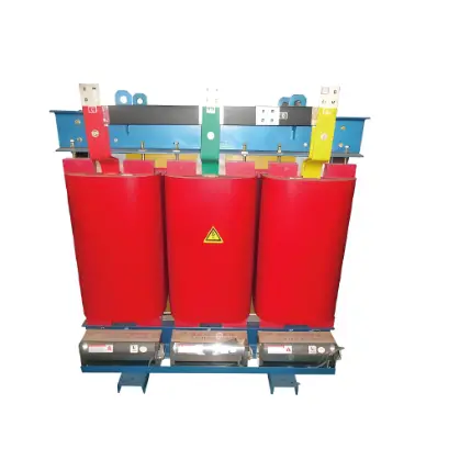
Protection measures of three-phase transformer

09/23/2024

Protection measures for use of three-phase transformers


Three-phase transformer may encounter various faults and abnormal working conditions during use, in order to ensure its safe and stable operation, a series of protective measures are usually taken. The following are several common protection measures for three-phase transformers according to the search results:


Gas protection


Gas protection is a protective measure used to reflect the internal failure of the transformer tank and the reduction of the oil level. When the fault in the tank produces slight gas or the oil level drops, the gas protection should be activated at the signal; When a large amount of gas is generated, the circuit breaker on each side of the transformer should be disconnected.


Longitudinal differential protection or current velocity break protection


This protection measure is used to reflect the short-circuit between the transformer winding and the lead line, and the single-phase grounding short-circuit between the neutral point direct grounding system winding and the lead line. It can quickly detect the fault and activate the protection mechanism, cut off the power and avoid the expansion of the fault.


Overcurrent protection


Overcurrent protection is used to reflect the external phase short circuit of the transformer, and as a backup protection for gas protection and differential protection (or current current break protection). This protection can be used as the last line of defense when the gas protection and differential protection fail, cutting off the power supply and protecting the transformer from damage.


Zero sequence current protection


Zero sequence current protection is used to protect the external single-phase grounding short circuit of the system with high grounding current. It detects the presence of zero sequence current and initiates protective action to avoid transformer damage due to ground failure.


Overload protection


Overload protection is used to reflect the symmetric overload of the transformer. This protection only acts on the signal and does not immediately cut off the power supply, but warns the staff that the transformer is overloaded and needs to be adjusted.


Overexcitation protection


Overexcitation protection is used to prevent transformer damage due to overexcitation. When the overexcitation of the transformer exceeds the allowable limit, the overexcitation protection will be activated, sending a signal or acting on the trip, limiting the degree of overexcitation.


Differential protection


Differential protection is an important protection measure, which can reflect the fault of transformer outlet line, bushing and internal short circuit. This kind of protection can be operated instantaneously on each side of the transformer circuit breaker, which is of great significance for the protection of transformer equipment.


Neutral point direct grounding protection


For the transformer directly grounded at the neutral point, when the single phase grounding fault occurs, it will produce a large short circuit current. The ground protection device determines whether the ground fault occurs by detecting the zero sequence current, and acts to remove the fault part in time.


Neutral point is not grounded or protected by arc suppression coil


For the transformer with ungrounded neutral or grounded by arc suppression coil, when the single-phase grounding fault occurs, the grounding current is small, and the zero-sequence voltage protection or insulation monitoring device is usually used to detect the grounding fault.


Temperature protection


The transformer will generate heat during operation, and when the temperature is too high, the insulation performance and service life of the transformer will be affected. The purpose of temperature protection is to monitor the temperature change of the transformer, and when the temperature exceeds the set value, send an alarm signal or act on the trip to prevent the transformer from overheating and damage.


The Electricity Encyclopedia is dedicated to accelerating the dissemination and application of electricity knowledge and adding impetus to the development and innovation of the electricity industry.

What is the difference between a dielectric and an insulator?
Dielectrics and insulators are distinguished primarily by their applications. One of the main differences is that a dielectric can store electrical energy by becoming polarized in an electric field, whereas an insulator resists the flow of electrons to prevent current conduction. Other key differences between them are outlined in the comparison chart below.Definition of DielectricA dielectric material is a type of insulator that contains few or no free electrons. When subjected to an electric fi
08/30/2025
Fault Analysis and Treatment of Oil-Immersed Transformers
Oil Leakage at Welded JointsOil leakage at welded joints primarily stems from poor welding quality, such as incomplete or detached welds, and defects like pinholes and gas pores. Although oil-immersed transformers are initially coated with solder and paint during manufacturing, potentially masking these issues temporarily, the defects tend to surface during operation. Additionally, electromagnetic vibration can cause weld cracks, leading to oil leakage.To resolve such leaks, the first critical s
08/29/2025
The Role of Transformers in Improving Power Quality
Transformers and Their Role in Enhancing Power QualityTransformers are fundamental components in power systems, playing a critical role in maintaining and improving electrical power quality. Power quality refers to the degree to which electrical energy conforms to defined parameters, including voltage stability, frequency, waveform integrity, and reliability. This article explores the significant contributions of transformers to power quality improvement.Voltage RegulationOne of the primary func
Vziman
08/19/2025
Transformer Connection Sections
Transformer Connection DesignationsThe transformer connection designation indicates the winding connection method and the phase relationship between the line voltages of the primary and secondary windings. It consists of two parts: letters and a number. The letters on the left denote the connection configurations of the high-voltage and low-voltage windings, while the number on the right is an integer from 0 to 11.This number represents the phase shift of the low-voltage winding's line voltage r
08/15/2025
Inquiry
Download
IEE-Business is dedicated to serving the personnel in the global power industry.
Join IEE-Business, not only can you discover power equipment and power knowledge, but also canhnd like - minded friends!