
1. Selection of Low - Voltage Current Transformer Configuration
There are many factors leading to wrong selection of low - voltage current transformers in civil construction projects. For example, common factors include design problems: the calculated coefficient designed for the load of electrical equipment is relatively large, or the transformation ratio of the current transformer is selected incorrectly. Such a series of reasons will affect the use of electrical equipment. Therefore, in the configuration and installation of low - voltage current transformers, the first issue to pay attention to is the selection of the configuration of low - voltage current transformers.
First, select the rated voltage and capacity. When selecting the rated voltage, pay attention to the magnitude of the rated voltage of the low - voltage current. The selected rated voltage should meet the needs of the line to be measured. In the selection of the rated capacity, it should be noted that the magnitude of the secondary capacity of the low - voltage current transformer has a great impact on the angle error. The actual rated secondary load of the selected current transformer is generally smaller than the rated secondary load.
Second, determine the rated primary current of the low - voltage current transformer. When the current transformer is in actual operation, it is necessary to ensure that the current of the actual load reaches a certain range. Generally, it needs to reach more than 50% of the primary current, and at least not less than 30%, so as to ensure the normal operation of the low - voltage current transformer and make the value obtained during metering more accurate. Generally, the magnitude of the primary current of the current transformer is closely related to the excitation current. When its magnitude is within the range of 20% to 120% of the rated current, the accuracy of the value obtained during metering is high.
Moreover, pay attention to the accuracy level when selecting. Generally, there are certain requirements for the accuracy level of the current transformer, and it should be at least 0.2 - 0.5S level, because the current of the S - level low - voltage current transformer is within the range of 1% to 120%, and the metering is relatively accurate.
2. Analysis of Key Points of Secondary Circuit Wiring
There are many issues to pay attention to in secondary circuit wiring. First, do a good job in the selection of wires. The selection of wires is related to the normal operation of the entire current transformer. The wire used between the electric energy meter box and the current transformer is a copper - core single - core insulated wire. In addition, there are certain requirements for the cross - sectional area of the connecting wire. The determination of its area size needs to be based on the magnitude of the rated secondary load of the current transformer. The cross - sectional areas of the voltage circuit and the current circuit should be controlled within certain values. For example, the cross - sectional area of the voltage circuit should be greater than 2.5 square millimeters, and the cross - sectional area of the current circuit should be greater than 4 square millimeters.
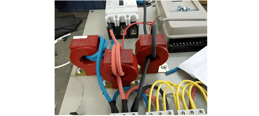
Second, there are certain requirements for the arrangement and phase color of the wires. When arranging the wires, number the voltage and current circuit wires. The numbering should be carried out according to the terminals on the drawing. The wires should be arranged in the positive phase sequence, and no winding phenomenon should occur during arrangement. For the phase color of the wires, for the three different types of wires L1, L2, and L3, different colors of wires are used respectively. L1 is yellow, L2 is green, and L3 is red. For the neutral wire, the color of the wire used is generally black, or light blue can be selected. Distinguishing wires by color facilitates the inspection work of inspectors and can detect whether the wires are connected accurately in a short time.
Moreover, pay attention to the wiring method. When wiring, connect the terminals of the transformer to the test terminal block. The two are directly connected, and there are no joints or contacts in between. Generally, for the secondary circuit of the electric energy meter, when every three current transformers are connected to each other, the number of required wires is as high as 6. In addition, a common wire will be used for connection to improve the accuracy of metering. Through the introduction of the voltage wire, the procedure is to first connect the voltage to the low - voltage three - phase four - wire electric energy through the current transformer. When introducing the voltage wire, select the method of separate access for connection, separate from the current wire. The other end of the voltage introduction wire is connected to the primary power supply terminal of the current transformer, and it is separated from the current busbar. It should not be led out from the connection screw positions at both ends of the busbar, and it must be ensured that the current transformer and the voltage introduction wire are properly connected.
3. Analysis of the Number of Turns of Primary Conductor Winding
The primary current of the low - voltage current transformer corresponds to the number of turns of primary winding. The determination of the number of winding turns needs to be based on the load current, the parameters marked on the current transformer, and the load current ratio. Such information is used to determine the number of winding turns, so that the determined number of winding turns is accurate. The number of winding turns is calculated based on the center of the current transformation ratio as the reference. The number of turns that do not pass through the center of the current transformer cannot be included in the calculation range. For example, the number of turns wound around the outside cannot be included in the turn calculation. The number of times the primary wire passes through the center hole of the current transformer is the number of turns.
When carrying out the configuration and installation work of the low - voltage current transformer, if economically permitted, try to select the coil - type current transformer. The main reason is that the coil - type transformer is different from the ordinary transformer, and it can ensure the correctness of the number of winding turns and avoid errors. The through - core bus - type transformer often has errors in the number of winding turns. More importantly, the primary conductor of the through - core bus - type transformer does not pass through the center part, and the metering accuracy is low.
4. Conclusion
In the installation work of the configuration of the low - voltage current transformer, the selection of the configuration is crucial and is closely related to the safety and reliability of the power system. Therefore, in the installation of the low - voltage current transformer, pay attention to the selection of the configuration of the low - voltage current transformer, the key points of the secondary circuit wiring, and the number of turns of the primary conductor winding, so as to ensure the smooth operation of the electrical equipment.


