Search


Common Fault Types and Countermeasures for Current Transformers (CT)

Common current transformer (CT) faults: open circuit, saturation, insulation failure, and countermeasures for reliable protection and metering.

Rockwill
Field: Manufacturing
10Year<
China
Add us on Google
 
The current transformer (CT) serves as the indispensable "eyes and ears" of the power system. It proportionally converts primary-side high currents into secondary-side low currents to supply signals for measuring instruments and protective relays. Because CTs are permanently connected in series with high-voltage circuits, a fault can cause anything from metering inaccuracies and protection maloperation to equipment burnout or even grid incidents. A thorough understanding of common CT fault types and their countermeasures is therefore essential for safe and stable power system operation.
iee-business

I. Secondary Open Circuit

Secondary open circuit is the most dangerous CT fault and demands the highest vigilance. Under normal operation the CT secondary is near short-circuit condition. Once opened, the entire primary current becomes the magnetizing current, driving the core into deep saturation and inducing extremely high voltage across the secondary terminals, which can easily puncture insulation or endanger personnel.

Symptoms — Loud humming or abnormal vibration from the CT body; sparking at the open terminal; connected ammeters or wattmeters reading zero or swinging erratically; in severe cases, smoking and overheating.

Countermeasures

  1. Immediately report to the dispatcher and withdraw protection schemes that may maloperate due to the open circuit (e.g., differential protection).
  2. Reduce the primary load current as much as possible to lower the induced voltage in the secondary circuit.
  3. Maintenance personnel must wear insulating boots and gloves, stand on an insulating mat, and use properly insulated tools to safely short-circuit the secondary at the dedicated test terminals near the CT.
  4. If the abnormality persists after shorting, or if an internal CT open circuit is suspected, de-energize the unit without delay and arrange for repair.

II. Internal Insulation Deterioration and Overheating

This type of fault is highly insidious and cumulative, often caused by manufacturing defects, prolonged moisture ingress, overloading, or external short-circuit current surges. Insulation aging and partial discharge progressively erode the equipment and may eventually lead to breakdown or explosion.

Symptoms — Dissolved gas analysis (DGA) shows abnormally elevated levels of characteristic gases (hydrogen, total hydrocarbons, acetylene); the enclosure becomes hot, smokes, or emits a burnt odor; crackling discharge sounds are heard from inside.

Countermeasures

  1. If oil test results seriously exceed limits or if smoking, fire, or other critical defects appear, immediately request de-energization and isolation.
  2. Never pull a disconnector to isolate the fault (disconnectors lack arc-quenching capability and may cause a short-circuit arc); always use a circuit breaker to interrupt the supply.
  3. If fire has broken out, use dry-powder extinguishers, CO₂ extinguishers, or dry sand. Water-based extinguishers are strictly prohibited.

III. Core Saturation and Accuracy Degradation

When the secondary burden is too high, the system short-circuit current is excessive, or the core material is substandard, the CT magnetic circuit may saturate. This distorts the output current waveform, seriously compromising measurement accuracy and protection reliability.

Symptoms — Inaccurate energy metering and abnormal line loss; protective relays maloperate or fail to operate.

Countermeasures

  1. Verify that the secondary burden is within the rated range; avoid operating the CT near saturation for extended periods.
  2. Conduct periodic excitation characteristic tests, ratio tests, and phase-angle tests to assess the magnetization state.
  3. If necessary, demagnetize the core or replace the CT with one having higher saturation resistance and a larger rated burden.

IV. Poor Contact and Secondary Circuit Abnormalities

Vibration, thermal expansion and contraction, or improper installation can loosen or corrode terminals, increasing contact resistance, generating heat, and interrupting signal transmission.

Symptoms — The data acquisition system reports a "loss of current" alarm; the output signal is unstable; connections show visible overheating, discoloration, or arcing.

Countermeasures

  1. Inspect and tighten loose terminals on site; clean oxidised or corroded contact surfaces.
  2. Use high-quality cables and terminals; perform regular infrared thermography to detect hot spots at connections.
  3. For faults inside relays or other components that cannot be handled directly, first short-circuit the CT secondary, then refer the issue to qualified personnel.

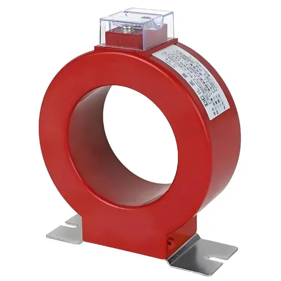
Low-Voltage (LV) Resin-Encapsulated Current Transformer - Indoor Window Type

Low-Voltage (LV) Resin-Encapsulated Current Transformer

V. Mechanical Damage and Environmental Aging

Prolonged exposure to high temperature, high humidity, or contaminated environments, or uneven stress during installation, can cause structural deformation, casting cracks, and insulation degradation.

Symptoms — Damaged enclosure; surface flashover; significantly reduced insulation resistance.

Countermeasures

  1. Keep the CT operating environment clean and dry; install dehumidifying heaters inside the cabinet when necessary.
  2. Strictly implement preventive tests (insulation resistance measurement, partial discharge test, AC withstand voltage test) to detect insulation deterioration at an early stage.
  3. Replace the unit promptly if severe mechanical damage or insulation degradation beyond acceptable limits is found.

Summary

The safe operation of current transformers directly affects power system stability. The cardinal rule in daily maintenance is "the CT secondary must never be opened." A multi-layered defence system combining routine inspection, periodic testing, and data analysis should be established: visual checks and infrared thermography capture surface anomalies, while insulation testing, partial discharge detection, and DGA accurately predict internal defects. Only by shifting from "post-fault repair" to "preventive action" can blind spots be eliminated and the safe, reliable, and economic operation of the grid be ensured.

Edited From:Garca

Give a tip and encourage the author!

Comments

Share your question or perspective
WhatsApp
Send inquiry
+86
Click to upload file
Download
Get the IEE Business Application
Use the IEE-Business app to find equipment, obtain solutions, connect with experts, and participate in industry collaboration anytime, anywhere—fully supporting the development of your power projects and business.
Login
or continue with
New here?
Register