
1. מבוא
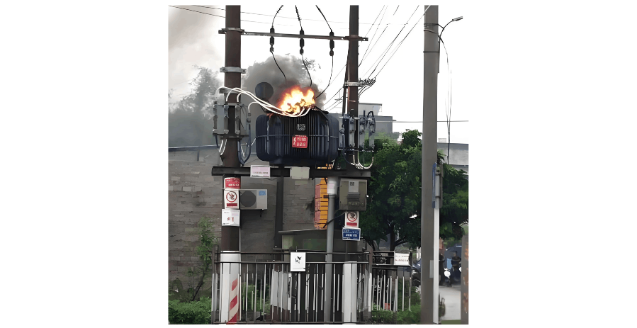
בגלל פעילות ממושכת, תקלות והפרעות במשרדי הפצת חשמל ברשתות החשמל הכפריות אינן ניתנות להימנעות לחלוטין. תקלות והפרעות אלו נגרמות בשל מגוון גורמים, כגון כוחות חיצוניים כמו פגיעה והתנגשות, ואסונות טבע בלתי נמנעים כגון פגיעת ברק.-meanwhile, בחלק מהאזורים הכפריים, קווי המתח הנמוך אינם מטופלים מספיק, מה שגורם לעובירה וקצר-مدار תכופים, מה שמוביל לשריפה של משרדי הפצת חשמל. זה הפך לגורם מרכזי לתקלות.
כדי למנוע את שריפת משרדי הפצת חשמל ולהפחית את תקלות הפעילות שלהם ברשתות החשמל הכפריות, מאמר זה סוקר ומחזיר כמה סוגים טיפוסיים של תקלות והסיבות להם במשרדי הפצת חשמל, חוקר אמצעי מניעה, חוקר והולך בעומק את הסיכונים והנקודות החלשות האפשריות במשרדי הפצת חשמל, מונע באופן יעיל ומגביל את התרחשות תקלות השריפה של משרדי הפצת חשמל, ובכך משפר את אמינות האספקה החשמלית ברשתות החשמל הכפריות.
כיום, המשרדים הפיזיים בשימוש ברשתות החשמל הכפריות הם בעיקר משרדי הפצת חשמל צפופי שמן. תקלות במשרדים הללו ממיינים בדרך כלל בין תקלות פנימיות ותקלות חיצוניות. תקלות פנימיות מתארות כל מיני תקלות המתפתחות בתוך תיבת המשרד. הסוגים העיקריים כוללים קצר-مدار בין הסלילים, קצר-مدار בין הסיבובים בסלילים, ותקלות חיבור שבהם הסלילים או ההוצאות נפגשים עם השטח החיצוני. תקלות חיצוניות הן כל מיני תקלות המתפתחות על הגליות המבודדות מחוץ לתיבת המשרד ועל ההוצאות שלהן. הסוגים העיקריים הם חיבור עקב פליטת או שבירה של הגליות המבודדות, וקצר-مدار בין-פאזה או חיבור של קווי היציאה במתח נמוך.
מאחר שהתקלות במשרדי הפצת חשמל מכסות טווח רחב, ישנם מספר רב של שיטות מיון ספציפיות. לדוגמה, מהפרספקטיבה של מעגלי חשמל, הם ממיינים בעיקר לתקלות מעגל, תקלות מסלול מגנטי ותקלות מסלול שמן. אם ממיינים בהתאם למבנה העיקרי של המשרד הפיזי, ניתן לחלק אותם לתקלות סליל, תקלות ליבה, תקלות איכות שמן ואביזרים. בדרך כלל, סוגי התקלות של המשרד הפיזי ממיינים בהתאם לאזורים נפוצים של תקלות, כגון תקלות מבודקות, תקלות ליבה, תקלות מחליפו תדרים, וכו'. בהם, תקלת קצר-مدار ביציאה של המשרד הפיזי היא זו שיש לה השפעה רצינית ביותר על המשרד עצמו וקצב התרחשות גבוה ביותר נכון לעכשיו. בנוסף, יש גם תקלות דליפות במשרדי הפצת חשמל, וכדומה. כל סוגי התקלות השונים יכולים לייצג תקלות חימיות, תקלות חשמליות, או תקלות חימיות ופליטה בו-זמנית. אבל, תקלת הדליפה של המשרד הפיזי לא תציג תכונות של תקלת חימית או חשמלית בתנאים נורמליים.
לכן, קשה לסווג את סוגי התקלות של משרדי הפצת חשמל במסגרת מסוימת. מאמר זה אימץ סוגים נפוצים וכלליים יחסית של תקלות במשרדי הפצת חשמל, כגון תקלות קצר-مدار, תקלות פליטה, תקלות מבודקות, תקלות ליבה, תקלות מחליפו תדרים, תקלות דליפות שמן-גז, תקלות נזק כוח חיצוני, ותקלות הגנה פוזילית. כל סוג מתואר בנפרד מבחינת הסיבה שלו ואת האמצעים הטכנולוגיים המתאימים.
2. ניתוח תקלות במשרדי הפצת חשמל
2.1 תקלות קצר-مدار
2.1.1 ניתוח סיבות התקלה
תקלות קצר-مدار במשרדי הפצת חשמל מתכוונים בעיקר לקצר-مدار ביציאה של משרדי הפצת חשמל, וכן קצר-مدار בין היציאות הפנימיות או הסלילים לקרקע, וקצר-مدار בין-פאזה, המוביל לתקלות.
במהלך הפעילות הנורמלית של משרדי הפצת חשמל, הנזק שנגרם מתקלות קצר-مدار ביציאה הוא ניכר. לפי סטטיסטיקות רלוונטיות, תקלות הנובעות ישירות מהשפעת זרם קצר-הمدار על משרדי הפצת חשמל ברשתות החשמל הכפריות מהוות בערך 40% מכלל התקלות. ישנם מקרים רבים כאלה. במיוחד כאשר קורה קצר-مدار במתח נמוך ביציאה של משרד הפצת חשמל, בדרך כלל יש להחליף את הסלילים. במקרים חמורים, עשויים להיות צריכים להחליף את כל הסלילים, מה שמביא לש."_consequences_and_losses_very_serious_. Therefore, it should be given sufficient attention.
The impacts of outlet short - circuits on distribution transformers mainly include the following two aspects:
Insulation Overheating Fault Caused by Short - Circuit Current
Due to inadequate maintenance of some rural low - voltage lines, overloading and short - circuits frequently occur. When a distribution transformer experiences a sudden short - circuit, its high - and low - voltage windings may simultaneously pass short - circuit currents dozens of times the rated value. This generates a large amount of heat, causing the distribution transformer to overheat severely and the coil temperature to rise rapidly, leading to insulation aging. When the distribution transformer's ability to withstand short - circuit current is insufficient and its thermal stability is poor, the insulation material of the distribution transformer will be severely damaged, resulting in breakdown and damage to the distribution transformer.
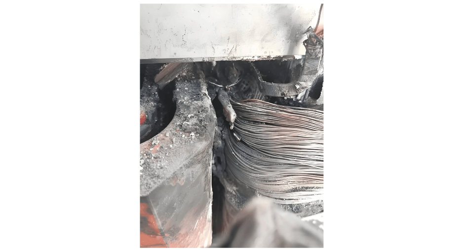
Winding Deformation Fault Caused by Short - Circuit Electrodynamic Force
When a distribution transformer is impacted by a short - circuit, if the short - circuit current is small and the fuse blows correctly, the winding deformation will be minor. If the short - circuit current is large and the fuse blows with a delay or fails to blow, the secondary side will generate a short - circuit current 20 - 30 times higher than the rated current. The primary side of the distribution transformer will inevitably generate a large current to counteract the demagnetizing effect of the secondary - side short - circuit current. The large current generates a significant mechanical stress inside the coil, causing the coil to compress, shift, or deform, the insulation pads and plates to loosen, the core clamping bolts to become slack, the high - voltage coil to distort or burst, and ultimately leading to a failure of the distribution transformer. At the same time, the windings are subjected to a relatively large electromagnetic torque, and the insulation material flakes off, exposing the wire body and causing inter - turn short - circuits. For minor deformations, if not repaired in a timely manner, such as restoring the position of the pads, tightening the pressure nails of the windings and the pull - plates and pull - rods of the yoke, and strengthening the clamping force of the lead - outs, the cumulative effect after multiple short - circuit impacts will also damage the distribution transformer.
2.1.2 Measures to Reduce Short - Circuit Faults
Optimization of Selection Requirements. When selecting a distribution transformer, choose one that can smoothly pass the short - circuit test. Reasonably determine the capacity of the distribution transformer and select its short - circuit impedance rationally. Try to use energy - efficient S11 - type distribution transformers and phase out high - energy - consumption transformers.
Optimization of Operating Conditions and Environment. Improve the insulation level of power lines, especially the insulation level of the low - voltage outlet lines of the distribution transformer over a certain distance. Meanwhile, raise the standards for the safety corridor and safety distance requirements of low - voltage lines to reduce the impact and hazards of nearby - area faults. This includes paying attention to the installation and maintenance quality of low - voltage dropper terminals (since the explosion of low - voltage terminals is mostly equivalent to a secondary short - circuit), preventing small animals from intruding, and improving the quality requirements for low - voltage fuses to prevent situations such as fuses not blowing.
Optimization of Operating Modes. When determining the operating mode, calculate the short - circuit current and limit its hazards. In particular, prevent the distribution transformer from operating under overload. Try to calculate and adjust the electrical load of the distribution transformer.
Improvement of Operation Management Level. First, prevent short - circuit impacts caused by misoperation. Strengthen the timely monitoring and maintenance of distribution transformers, promptly detect the degree of deformation of distribution transformers, and ensure their safe operation. At the same time, increase the inspection efforts on the power consumption of users in the distribution transformer area to prevent overloading problems caused by user power theft.
2.2 Discharge Faults
Based on the energy density of the discharge, the discharge faults of distribution transformers are commonly classified into partial discharge, spark discharge, and high - energy discharge. Discharge has two types of destructive effects on insulation: one is that the discharge particles directly bombard the insulation, causing local insulation damage and gradually expanding it until the insulation breaks down. The other is that the chemical action of active gases such as heat, ozone, and nitrogen oxides generated by the discharge corrodes the local insulation, increases the dielectric loss, and ultimately leads to thermal breakdown.
2.2.1 Partial Discharge Faults of Distribution Transformers
Partial discharge refers to a non - through - type discharge phenomenon that occurs at the edges of air gaps, oil films, or conductors within the insulation structure under the action of voltage. At the beginning, partial discharge is a low - energy discharge. When this kind of discharge occurs inside a distribution transformer, the situation is relatively complex. According to different insulation media, partial discharge can be divided into partial discharge in bubbles and partial discharge in oil. According to insulation locations, it includes partial discharge in cavities of solid insulation, at electrode tips, in oil - corner gaps, in oil gaps between oil and insulation paperboards, and along the surface of solid insulation in oil. The reasons for partial discharge are as follows:
When there are bubbles in the oil or cavities in the solid insulation material, due to the small dielectric constant of the gas, it bears a high electric field strength under alternating voltage, but its withstand voltage strength is lower than that of oil and paper insulation materials. Therefore, discharge is likelyly to occur first in the air gap.
Influence of external environmental conditions. For example, if the oil treatment is incomplete and bubbles precipitate from the oil, it will cause discharge.
Due to poor manufacturing quality. For example, discharge occurs at some parts with sharp corners. Bubbles, debris, and moisture are introduced, or due to external temperature - related factors such as paint nodules, they bear a relatively large electric field strength.
Discharge caused by poor contact between metal parts or conductors. Although the energy density of partial discharge is not large, if it develops further, it will form a vicious cycle of discharge, ultimately leading to the breakdown or damage of the equipment and causing serious burnout accidents.
2.2.2 Spark Discharge Faults of Distribution Transformers
Generally, spark discharge does not quickly cause insulation breakdown. It is mainly reflected in abnormal oil chromatographic analysis, an increase in partial discharge quantity, or light gas. It is relatively easy to detect and handle, but sufficient attention should be paid to its development. There are mainly two reasons for spark discharge:
Spark Discharge Caused by Floating Potential. In high - voltage power equipment, a certain metal part, due to structural reasons or poor contact during transportation and operation, is disconnected and is located between the high - voltage and low - voltage electrodes, dividing the voltage according to its impedance. The potential to the ground generated on this metal part is called the floating potential. The electric field strength near an object with a floating potential is relatively concentrated, often gradually burning out the surrounding solid dielectric or carbonizing it.
It also causes the insulating oil to decompose a large amount of characteristic gases under the action of the floating potential, resulting in an abnormal result of the insulating oil chromatographic analysis. Floating discharge may occur in metal parts at high potential inside the distribution transformer, such as the regulating winding, when the grading ball of the bushing and the no - load tap - changer shift fork have a floating potential. For parts at ground potential, such as the silicon steel sheet magnetic shielding and various metal bolts for fastening, if their connection to the ground is loose or detached, it will lead to floating - potential discharge. Poor contact at the end of the high - voltage bushing of the distribution transformer can also form a floating potential and cause spark discharge.
Spark Discharge Caused by Impurities in Oil
The main cause of spark discharge faults in distribution transformers is the influence of impurities in the oil. These impurities are composed of moisture, fibrous substances (mainly damp fibers), etc. The dielectric constant ε of water is approximately 40 times that of the distribution transformer oil. In an electric field, the impurities are first polarized and attracted to the area with the strongest electric field intensity, namely near the electrodes, and are arranged in the direction of the electric field lines. Thus, an impurity "bridge" is formed near the electrodes.
The conductivity and dielectric constant of the "bridge" are both greater than those of the distribution transformer oil. According to the principles of electromagnetic fields, the presence of the "bridge" distorts the electric field in the oil. Since the dielectric constant of the fibers is small, the electric field in the oil at the ends of the fibers is strengthened. Therefore, the discharge first occurs and develops in this part of the oil. The oil dissociates under a high - field - strength environment, decomposing into gases, which causes the bubbles to increase in size and the dissociation to strengthen. Subsequently, the process gradually develops, leading to spark discharge in the entire oil gap through the gas channel. So, spark discharge may occur at a relatively low voltage.
If the distance between the electrodes is not large and there are enough impurities, the "bridge" may connect the two electrodes. At this time, due to the relatively high conductivity of the "bridge", a large current flows along the "bridge" (the magnitude of the current depends on the capacity of the power supply), causing the "bridge" to heat up intensely. The moisture and the nearby oil in the "bridge" boil and vaporize, creating a gas channel - the "bubble bridge", and spark discharge occurs.
If the fibers are not damp, the conductivity of the "bridge" is very small, and its influence on the spark discharge voltage of the oil is also relatively small; conversely, the influence is greater. Therefore, the spark discharge of the distribution transformer oil caused by impurities is related to the heating process of the "bridge". When an impulse voltage acts or the electric field is extremely non - uniform, it is not easy for the impurities to form a "bridge", and their effect is only limited to distorting the electric field. The spark discharge process mainly depends on the magnitude of the applied voltage.
2.2.3 Arc Discharge Faults of Distribution Transformers
Arc discharge is a high - energy discharge, which is commonly seen as insulation breakdown between winding turns or layers. Other common faults include lead breakage, flashover to the ground, and arcing of tap - changers.
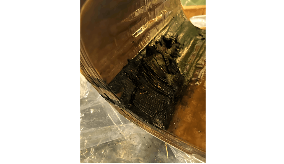
Influence of Arc Discharge. Due to the high energy density of arc discharge faults, gas is generated rapidly. It often impacts the dielectric in the form of electron avalanches, causing the insulating paper to perforate, char, or carbonize, deforming or melting and burning the metal materials. In severe cases, it may cause equipment damage or even explosions. Such accidents are generally difficult to predict in advance and have no obvious omens, often emerging in a sudden manner.
Gas Characteristics of Arc Discharge. After an arc discharge fault occurs, the distribution transformer oil also carbonizes and turns black. The main components of the characteristic gases in the oil are H2 and C2H2, followed by C2H6 and CH4. When the discharge fault involves solid insulation, CO and CO2 will also be generated.In summary, the three forms of discharge have both differences and certain connections. The differences refer to the discharge energy level and gas composition, while the connection is that partial discharge is a precursor to the other two forms of discharge, and the latter two are inevitable results of the development of the former. Since the faults occurring inside distribution transformers are often in a state of gradual development, and most of them are not single - type faults, but rather one type is accompanied by another type, or several types occur simultaneously. Therefore, more careful analysis and specific treatment are required.
2.3 Insulation Faults
Currently, the most widely used distribution transformers in rural power grids are oil - immersed transformers. The insulation of a distribution transformer refers to the insulation system composed of its insulation materials. It is a fundamental condition for the normal operation of the distribution transformer, and the service life of the distribution transformer is determined by the lifespan of the insulation materials (such as oil - paper or resin). Practical experience has proven that most of the damage and faults of distribution transformers are caused by the damage of the insulation system.
Therefore, protecting the normal operation of the distribution transformer and strengthening the reasonable maintenance of the insulation system can, to a large extent, ensure a relatively long service life for the distribution transformer. Preventive and predictive maintenance are the keys to extending the service life of distribution transformers and improving power supply reliability.
In oil - immersed distribution transformers, the main insulation materials are insulating oil and solid insulation materials such as insulating paper, cardboard, and wooden blocks. The so - called aging of the distribution transformer insulation means that these materials decompose under the influence of environmental factors, reducing or losing their insulation strength.
2.3.1 Solid Paper Insulation Faults
Solid insulation is one of the main components of the insulation of oil - immersed distribution transformers, including insulating paper, insulating board, insulating pad, insulating coil, insulating binding tape, etc. Its main component is cellulose. After the insulating paper ages, its degree of polymerization and tensile strength gradually decrease, and water, CO, and CO2 are generated. In addition, furfural (furfuraldehyde) is also produced. Most of these aging products are harmful to electrical equipment. They can reduce the breakdown voltage and volume resistivity of the insulating paper, increase the dielectric loss, decrease the tensile strength, and even corrode the metal materials in the equipment.
2.3.2 Liquid Oil Insulation Faults
Reasons for the Deterioration of Distribution Transformer Oil
Contamination means that moisture and impurities are mixed into the oil. These are not oxidation products of the oil. The insulation performance of contaminated oil deteriorates, the breakdown electric field strength decreases, and the dielectric loss angle increases.
Deterioration is the result of oil oxidation. This oxidation does not only refer to the oxidation of hydrocarbons in pure oil but also includes the acceleration of the oxidation process by impurities in the oil, especially copper, iron, and aluminum metal shavings.
Oxygen comes from the air inside the distribution transformer. Even in a fully - sealed distribution transformer, there is still about 0.25% of oxygen by volume. Oxygen has a relatively high solubility, so it occupies a relatively high proportion among the dissolved gases in the oil.
When the distribution transformer oil oxidizes, moisture as a catalyst and heat as an accelerator cause the distribution transformer oil to generate sludge. Its main impacts are as follows: under the action of the electric field, the sediment particles are large; the impurities concentrate in the area with the strongest electric field, forming a conductive "bridge" for the insulation of the distribution transformer; the sediment is not uniform but forms separate slender strips, and it may be arranged in the direction of the electric field lines, which undoubtedly hinders heat dissipation, accelerates the aging of insulation materials, and leads to a decrease in insulation resistance and insulation level.
The Process of Distribution Transformer Oil Deterioration
During the deterioration process of the oil, the main products in each stage are peroxides, acids, alcohols, ketones, and sludge.In the early deterioration stage, the peroxides generated in the oil react with the insulating fiber materials to form oxidized cellulose, which deteriorates the mechanical strength of the insulating fibers, causing embrittlement and insulation shrinkage. The generated acids are a kind of viscous fatty acid. Although its corrosiveness is not as strong as that of mineral acids, its growth rate and impact on organic insulation materials are significant.
In the later deterioration stage, sludge is generated. When acids erode copper, iron, insulating paint, and other materials, sludge is produced. It is a viscous, asphalt - like polymeric conductive substance that can moderately dissolve in the oil. Under the action of the electric field, it is generated very quickly and adheres to the insulation materials or the edges of the distribution transformer tank, deposits in the oil pipes and radiator fins of the cooler, etc., increasing the operating temperature of the distribution transformer and reducing its electrical withstand strength.
The oxidation process of the oil is composed of two main reaction conditions. One is that the acid value in the distribution transformer oil is too high, making the oil acidic. The other is that the oxides dissolved in the oil are transformed into compounds insoluble in the oil, gradually deteriorating the quality of the distribution transformer oil.
2.3.3 Winding Insulation Moisture Ingress
Winding insulation moisture ingress is mainly caused by poor - quality insulating oil or a decrease in the oil level. The main reasons are as follows:
Before the distribution transformer is put into operation, if it is in a humid place or a rainy area with high humidity, moisture will invade and cause the insulation to get damp.
During storage, transportation, and operation, improper maintenance may lead to moisture, impurities, or other oil contaminants mixing into the distribution transformer oil, greatly reducing the insulation strength.
During the manufacturing process, if the inner layer of the winding is not impregnated thoroughly and dried completely, or if the winding lead joints are not welded properly, incomplete insulation may cause inter - turn and inter - layer short - circuits. When approaching or reaching the service life, the insulation naturally becomes charred and black, and the insulation characteristics decline, which is the main cause of faults in old distribution transformers.
In some old distribution transformers that have not been maintained for a long time, for various reasons, the oil level drops, and the insulating oil comes into extensive and long - term contact with the air. A large amount of moisture in the air enters the insulating oil, reducing the insulation strength.
2.3.4 Main Factors Affecting Distribution Transformer Insulation Faults
The main factors affecting the insulation performance of distribution transformers include temperature, humidity, oil protection method, and over - voltage influence.
Influence of Temperature. Power distribution transformers use oil - paper insulation. At different temperatures, there are different equilibrium relationship curves for the water content in the oil and paper. Generally, when the temperature rises, the water in the paper is released into the oil; conversely, the paper absorbs water from the oil. Therefore, when the temperature is relatively high, the micro - water content in the insulating oil of the distribution transformer is relatively large; otherwise, it is small.
The service life of a distribution transformer depends on the degree of insulation aging, and the aging of the insulation depends on the operating temperature.
Influence of Humidity. The presence of moisture will accelerate the degradation of cellulose. Trace amounts of moisture in the insulating oil are one of the important factors affecting insulation characteristics. The presence of trace moisture in the insulating oil is extremely harmful to the electrical and physical - chemical properties of the insulation medium. Moisture can reduce the spark discharge voltage of the insulating oil, increase the dielectric loss factor tgδ, accelerate the aging of the insulating oil, and deteriorate the insulation performance. Equipment moisture ingress not only reduces the operational reliability and service life of electrical equipment but may also cause equipment damage and even endanger personal safety.
Influence of Over - Voltage.
Influence of Transient Over - Voltage. The phase - to - ground voltage generated during the normal operation of a three - phase distribution transformer is 58% of the phase - to - phase voltage. However, when a single - phase fault occurs, the voltage on the main insulation for a neutral - grounded system will increase by 30%, and for a non - neutral - grounded system, it will increase by 73%. Therefore, the insulation may be damaged.
Influence of Lightning Over - Voltage. Due to the steep wavefront of lightning over - voltage, the voltage distribution on the winding insulation (inter - turn and insulation) is very uneven. It may leave discharge traces on the insulation, thus damaging the solid insulation, such as the explosion of low - voltage terminal insulators.


