Contactors are used to close and open loads that require such operations during normal use, particularly for specific activities like medium-voltage public lighting and industrial electric motors.
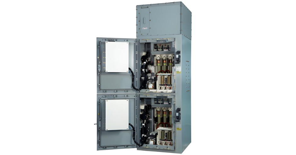
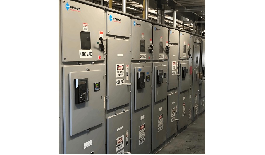
The medium-voltage contactor + fuse combination controller (F-C) can control motors up to 12 kV. However, medium-voltage controllers are also suitable as feeders for other types of loads, especially transformers. For such loads, contactors are usually modified to include mechanical latching, so that the contactor does not open automatically when the system voltage collapses.
Mechanically latched contactors are basically the same in structure as electromagnetically held contactors. Nevertheless, instead of relying on a continuously energized main coil to keep the contactor closed, mechanically latched contactors use mechanical latching to maintain the closed state. In essence, mechanically latched contactors simulate medium-voltage circuit breakers. However, it must be kept in mind that there are distinct differences between contactors and circuit breakers.
Considerations for Control Circuits
Once a traditional electromagnetically held contactor is closed, it remains closed as long as the main coil is energized. Most commonly, the control power supply for the main coil circuit is a control power transformer, which is an integral part of the entire controller. Therefore, for motor loads, when the system voltage collapses, the motor will disconnect automatically, thereby preventing damage to the motor.
In contrast, mechanically latched contactors remain closed when the system voltage collapses. This is particularly necessary when the load is of a type that needs to be automatically re-energized when the system voltage is restored, such as lighting transformers.
Electromagnetically held contactors open when the contacts in the main coil control circuit open. On the other hand, mechanically latched contactors are unlocked by the closing of contacts in the latching circuit, allowing the contactor to open. Thus, the control required for mechanically latched contactors is somewhat similar to that of medium-voltage circuit breakers.
Mechanically latched contactors require a reliable control power supply for tripping. A direct current (battery) power supply is preferred, but if the only control power supply is a control power transformer connected to the primary voltage source, an alternating current capacitor tripping device is suitable for use.
The closing circuit should use momentary contact buttons so that the main coil is energized only during the closing period. Similarly, the tripping (latch release) circuit should use momentary contact buttons. For automatic tripping of protective relays, a normally open contact should be connected in the tripping (latch release) circuit, and a normally closed contact from the protective relay should be connected in the closing circuit. The purpose of the normally closed relay contact in the closing circuit is to ensure that the main coil circuit is de-energized during tripping. It is also desirable to include a lockout (86) relay function, either through the 86 function in some multi-functional microprocessor relays or via a separate lockout relay.
Importantly, the user's external control circuit should not include holding contacts in the closing circuit. Mechanically latched contactors operate in the same way as electromagnetically held contactors, with the addition of a mechanical latch. If the main coil circuit is energized continuously, the contactor will remain closed even if the tripping latch is operated.
Sources vary in their estimates of the amount of time that must be allowed between fault interruption and subsequent re-energization. Most sources indicate that there must be at least six cycles between the interruption of the arc (when opening) and contact closure in the subsequent closing operation.
Short-Circuit and Overload Considerations
Contactors used to supply power to transformers differ from those used to supply power to motors solely in the characteristics of the current-limiting fuses. Fuses used to protect motor circuits are Class M fuses, whose protective characteristics are suitable for the application requirements of motors. For transformer feeders, the fuses should be Class T fuses, designed to provide appropriate protection for transformers.
Contactors without fuses have only limited interrupting capacity. Therefore, contactors must always be used in combination with current-limiting fuses. The combination of a contactor (which interrupts normal load current and moderate overload current) and a current-limiting fuse (which interrupts currents exceeding the capacity of the contactor alone) provides complete overcurrent and short-circuit interrupting capacity.
Overcurrent relays should be used to provide protection against moderate overload currents, so as to avoid unnecessary fuse operation. This protection must be coordinated with the continuous current-carrying capacity of the fuse-contactor combination. Since fuses generate a significant amount of heat, it is not uncommon for fuses to be sized somewhat larger than recommended for continuous current. Therefore, overcurrent relays provide overload protection not only for the transformer but also for the fuse-contactor combination. This is appropriate because the function of the fuse is to provide short-circuit protection, not overload protection.
Single-Phase Protection
Modern motor overload protection devices usually include a protection function to automatically disconnect the motor when one phase of the input power is lost. However, for non-motor feeders, this "single-phase protection" may not be necessary or desirable. For example, capacitor or lighting loads are usually not damaged by single-phase conditions. Nevertheless, users should consider whether single-phase protection is appropriate. The most common method of implementing this function is to provide a fuse trip accessory, which is mechanically actuated by a plunger on the current-limiting fuse. With this option, when any single primary current-limiting fuse operates, the indicator plunger on the fuse actuates a trip lever, causing the contactor to open.
Other Application Considerations
Mechanically latched contactors share many application characteristics with electromagnetically held contactors. Unlike circuit breakers, contactors are designed for frequent operation, with 200,000 electrical operations. The size of the transformer that can be powered from a contactor is, of course, limited by the available fuses (especially at 7.2 kV) and the continuous current capacity of the contactor.
Contactors are designed to have low energy control power requirements. Therefore, their closing and opening speeds may be relatively slow. A typical closing time is 40 ms for 400 A and 70 ms for 720 A, while the opening time is 90 ms for 400 A and 35 ms for 720 A. Although these times are much longer than the operating times of circuit breakers, they usually do not require any special consideration for control circuits or system operating procedures. Latched contactors are integrated into the design of medium-voltage controllers, eliminating the transition sections and large switchgear enclosures required for circuit breakers. Since mechanically latched contactors use fuses for short-circuit protection, fuses may operate in the event of a severe fault. If this occurs, the downtime associated with replacing the fuses is longer than that required when using circuit breakers. However, experience has shown that severe faults are relatively rare, so this is unlikely to be a major issue.
Summary
Contactors have been used to supply power to transformers and other non-motor loads for decades, and their usage has increased significantly in recent years. The use of mechanically latched contactors is particularly appropriate when transformers are powered by medium-voltage contactors.


