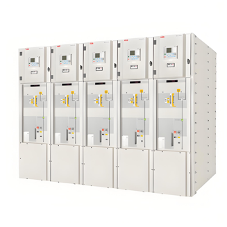
According to insulation type, ring main units (RMUs) can be categorized as gas-insulated or air-insulated. The former installs primary circuit components in a sealed metal enclosure filled with low-pressure gas (primarily SF₆ or mixed gases) as the insulating medium, using cable terminals for incoming and outgoing lines. Due to superior insulation, compact size, and modular design, they are widely used in 10kV outdoor distribution substations and prefabricated transformer stations. However, their fully insulated and compact nature limits applicability in certain typical substation layouts.
1 Issues with Gas-Insulated RMUs
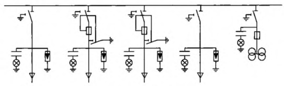
Figure 1 illustrates a typical distribution substation design, where the load switch-fuse combination cabinet requires a lightning arrester, and the voltage transformer (VT) cabinet requires two 10/0.1/0.22kV cast resin VTs. If projects select gas-insulated RMUs like Schneider’s RM6 or ABB’s Safenng, the design requirements cannot be fully met.
1.1 Difficulty Installing Arresters in Load Switch-Fuse Cabinets
For load switch incoming/outgoing cabinets, both brands provide sufficient cable compartment space with Type-C bushings (IEC 60137-compliant), allowing plug-in T-type cable accessories and plug-in arresters. In load switch-fuse cabinets:
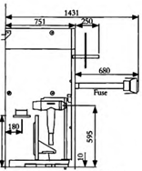
Safenng: Horizontally mounted fuses (Figure 2) preserve cable space, enabling plug-in arrester installation.
RM6: Vertically mounted fuses (Figure 3) occupy cable space, with Type-A bushings limiting accessories to elbow/straight types. No space exists for plug-in arresters, and no market-ready arresters compatible with elbow/straight accessories are available.
1.2 Difficulty Installing VTs in VT Cabinets
Standard VT cabinets require three HV fuse units and two single-phase VTs in a V-connected configuration (dual-winding, 10/0.1kV for metering, 10/0.22kV for power supply; ≥1000VA secondary output). Air-insulated RMUs (e.g., Schneider SM6) offer ample space (500×840×950mm). In contrast, gas-insulated RMUs feature compact cable compartments (~400×350×700mm), insufficient for cable accessories, connection cables, exposed fuses, VTs, or 125mm phase-to-phase/ground clearance.
Manufacturers typically add an empty cabinet beside the load switch cabinet to house VTs and fuses, connecting them via cables. However, this compromises:
Safety during VT maintenance due to lack of mechanical interlocks.
Compactness and aesthetics of outdoor stations.
2 Lightning Arrester Installation Solutions
2.1 Omitting Arresters
DL/T 620-1997 Overvoltage Protection and Insulation Coordination for AC Electrical Installations mandates surge arresters for cables >50m connected to overhead lines. For ≤50m cables, arresters may be installed at one end only. However, the standard does not explicitly require arresters on plug-in cable heads of 10kV gas-insulated RMUs.
Modern urban buildings feature extensive lightning protection networks, reducing lightning strike risks. Overhead cable connections are rare in cities, making direct lightning surges to cable cores unlikely. International practices (e.g., T-type arrester accessories) are often omitted in urban areas. Gas-insulated RMUs in Zhejiang Province operate reliably for years without arresters. Therefore, arresters can be omitted for urban gas-insulated RMU substations.
2.2 Arrester Selection Criteria
For suburban/rural grids with overhead-connected cables >50m, arresters must be installed. For pure load switch units, most products suffice. For load switch-fuse units, specify horizontally arranged fuses to reserve arrester space, avoiding retrofitting issues.
3 Voltage Transformer Installation Solutions
VT cabinet miniaturization requires resolving electrical insulation and space constraints.
3.1 Solving Electrical Insulation
Using standard fuses/VTs from air-insulated RMUs in gas-insulated compartments violates clearance standards. The solution is adopting insulation-compliant components, such as the JSZV16-10R VT. Features include:
Integrated American-style cable accessories for full insulation.
Built-in replaceable fuses at HV terminals.
Rated voltage: 10/0.1/0.22kV.
Wiring configuration:
Load switch side: European-style touchable T-type accessories.
VT side: American-style 20kV touchable elbow accessories (compatible with VT fuses).
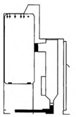
Figure 4 shows the VT and American-style accessories.
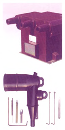
All components are fully insulated and touchable. The limitation is the JSZV16-10R VT’s size (designed for compact outdoor RMUs), restricting 220V output to ≤2×400VA—sufficient for DC battery charging and lighting.
3.2 Solving Space Constraints
Validated layouts confirm insufficient space for VTs with cable accessories. Two solutions were tested:
Top-mounted VT box: External cables and unsafe VT maintenance (violating interlocks).
Bottom-mounted VT base (implemented):
Extends the cable compartment downward.
Height: 400mm, compatible with 700mm-high cable compartments.
Enables mechanical interlocking for maintenance.
Result: This design ensures safe installation and maintenance while preserving gas-insulated RMU compactness.


