Intelligent Control Module Solution for AC Contactor Voltage Sag Ride-Through

1.Design Background and Requirement Analysis
During power system operation, voltage sags—characterized by a sudden drop in RMS voltage to 10%–90% of the rated value lasting from 10 ms to 1 minute—often occur due to lightning strikes, short-circuit faults, or the starting of large equipment. Such events can cause traditional AC contactors to trip, resulting in unplanned shutdowns in continuous production processes and significant economic losses.
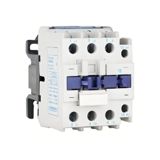
Although several intelligent control solutions (e.g., high-voltage DC starting, PWM control) have been proposed, a key limitation remains: the failure to integrate automatic module fault transition functionality with voltage sag ride-through capability. To address this issue, this solution uses the CDC17-115 AC contactor as the control target and designs an intelligent control module with fault redundancy to maintain production continuity even in the event of module failure.
2. Module Working Principle and System Design
2.1 Overall Operational Logic Architecture
The intelligent control module adopts a dual-mode power supply design to ensure reliable operation under various conditions:
|
Operating State |
Power Supply Method |
Core Function |
Trigger Condition |
|
Normal Operation |
DC Supply (via control module) |
Silent DC operation, voltage sag ride-through |
Fault protection circuit detects no abnormality |
|
Module Fault |
AC Supply (via contact switch) |
Maintain production, issue alarm signal |
Electronic circuit fault or coil DC under-voltage |
|
Voltage Sag |
Activate ride-through function |
Maintain contactor pull-in state |
Sampled voltage drops below 60% of rated value |
|
Voltage Recovery |
Deactivate ride-through function |
Resume normal low-voltage holding |
Voltage recovers within n ms (adjustable) |
|
Voltage Not Recovered |
Contactor breaks |
Safe shutdown |
Voltage sag exceeds n ms without recovery |
2.2 Key Component Technical Details
2.2.1 Switching Power Supply Design
A high-performance switching power supply serves as the core power unit with the following features:
- Core Architecture: Pulse-width modulation IC (switching frequency 132 kHz), MOSFET (MTD1N80E), special transformer (primary inductance 900 μH, leakage inductance 15 μH, turns ratio 0.11), and π-type output filter (L3, C2, C3)
- Multi-Protection Functions: Input overvoltage/undervoltage, output overvoltage/overcurrent/short-circuit/overheat protection, integrated soft-start and frequency jitter technology
- Performance:
- Stable load start-up time < 35 ms, supports rapid switching between ride-through and normal states
- Automatically limits power during short circuits and quickly stabilizes after fault clearance
- Triggers overvoltage protection and immediately shuts off PWM output upon feedback loop open
Table 1: Impact of Filter Parasitic Parameters on Short-Circuit Recovery Voltage
|
Simulation Condition |
R4/mΩ |
R3/mΩ |
R5/mΩ |
Umax/V |
Umin/V |
|
Only varying filter capacitor parasitic resistance |
10 |
100 |
300 |
14.78 |
7.41 |
|
Only varying filter capacitor parasitic resistance |
10 |
20 |
70 |
8.89 |
4.79 |
|
Only varying filter inductor parasitic resistance |
10 |
100 |
300 |
14.78 |
7.41 |
|
Only varying filter inductor parasitic resistance |
800 |
100 |
300 |
6.11 |
6.06 |
2.2.2 Fault Transition Circuit Design
An innovative combination of contact and contactless switches is used:
- Structural Design: Contact switches handle full breaking and isolation functions for high-power switching; power electronic switches enable arc-free, high-frequency operation
- Intelligent Transition Logic:
- AC power is supplied via normally closed contacts during initial power-up
- Automatically switches to DC supply mode during normal operation
- Upon fault detection, deactivates the contact switch drive; resumes AC direct supply after reset to ensure continuity
- Contact Protection Technology: Uses a universal AC/DC absorption suppression circuit (diode RC + bidirectional TVS diode D3) to effectively clamp overvoltage, dissipate inductive magnetic energy, and significantly reduce arcing
2.2.3 Transition Process Optimization
- AC-to-DC Transition: Applies full-wave rectified pulsating voltage via power electronic switches, delays 10 ms before switching to low-voltage DC, effectively preventing core rebound; tested transition is smooth and vibration-free
- DC-to-AC Transition: Cuts off DC upon fault and intelligently introduces AC supply; arc energy is freewheeled through reverse diodes during transition, with phase-angle control to avoid voltage spike interference
- Parameter Optimization (based on simulation results):
- Resistors (R2, R3): Smaller resistance values result in slower voltage amplitude decay but do not affect transition phase angle
- Capacitors (C1, C2): Smaller capacitance values yield higher oscillation decay frequency (f = 174.7 Hz at C = 2 μF; f = 795.4 Hz at C = 0.1 μF)
3. Simulation and Experimental Verification
3.1 Simulation Analysis
System simulations were conducted using Multisim software, including:
- Switching power supply start-up characteristics and protection performance simulation
- Analysis of resistance, capacitance, and phase angle effects on voltage oscillation during transition
- Evaluation of parasitic parameter impacts on system stability
3.2 Experimental Verification
Tests on the CDC17-115 AC contactor confirmed:
- Switching power supply no-load/full-load (50 A contactor) waveforms meet design expectations
- Protection mechanisms respond quickly and effectively under short-circuit/feedback open-circuit faults
- Transition processes are smooth, with no core vibration, and all functions meet design requirements
4. Core Advantages and Conclusion
- High-Performance Switching Power Supply: Compact size, high efficiency, and comprehensive protection functions significantly enhance electrical reliability, making it ideal for smart electrical applications.
- Intelligent Fault Transition: Innovative design combining contact and contactless switches ensures timely switching to AC operation during module faults, guaranteeing continuous power supply to the contactor system.
- Efficient Energy Management: Universal AC/DC absorption suppression circuit effectively converts overvoltage and arc energy during transitions into stable electromagnetic force, ensuring uninterrupted production.
- Voltage Sag Ride-Through Capability: Automatically activates when system voltage drops to 60% of the rated value, maintaining reliable contactor pull-in to avoid unplanned shutdowns.
This solution successfully integrates module fault transition with voltage sag ride-through functionality, providing a highly reliable power assurance solution for continuous production processes and effectively mitigating downtime caused by voltage sags.