1. Design Background and Requirement Analysis
In the operation of power systems, voltage sags—characterized by a sudden drop in RMS voltage to 10%–90% of the rated value lasting from 10 ms to 1 minute—often occur due to lightning strikes, short-circuit faults, or the starting of large equipment. Such events can cause traditional AC contactors to trip, resulting in unplanned shutdowns in continuous production processes and significant economic losses.
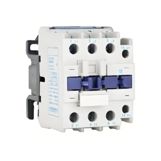
Although several intelligent control solutions (e.g., high-voltage DC starting, PWM control) have been proposed, a key limitation remains: the failure to integrate automatic module fault transition functionality with voltage sag ride-through capability. To address this issue, this solution uses the CDC17-115 AC contactor as the control target and designs an intelligent control module with fault redundancy to maintain production continuity even in the event of module failure.
2. Module Working Principle and System Design
2.1 Overall Operational Logic Architecture
The intelligent control module adopts a dual-mode power supply design to ensure reliable operation under various conditions:
|
Operating State |
Power Supply Method |
Core Function |
Trigger Condition |
|
Normal Operation |
DC Supply (via control module) |
Silent DC operation, voltage sag ride-through |
Fault protection circuit detects no abnormality |
|
Module Fault |
AC Supply (via contact switch) |
Maintain production, issue alarm signal |
Electronic circuit fault or coil DC under-voltage |
|
Voltage Sag |
Activate ride-through function |
Maintain contactor pull-in state |
Sampled voltage drops below 60% of rated value |
|
Voltage Recovery |
Deactivate ride-through function |
Resume normal low-voltage holding |
Voltage recovers within n ms (adjustable) |
|
Voltage Not Recovered |
Contactor breaks |
Safe shutdown |
Voltage sag exceeds n ms without recovery |
2.2 Key Component Technical Details
2.2.1 Switching Power Supply Design
A high-performance switching power supply serves as the core power unit with the following features:
Table 1: Impact of Filter Parasitic Parameters on Short-Circuit Recovery Voltage
|
Simulation Condition |
R4/mΩ |
R3/mΩ |
R5/mΩ |
Umax/V |
Umin/V |
|
Only varying filter capacitor parasitic resistance |
10 |
100 |
300 |
14.78 |
7.41 |
|
Only varying filter capacitor parasitic resistance |
10 |
20 |
70 |
8.89 |
4.79 |
|
Only varying filter inductor parasitic resistance |
10 |
100 |
300 |
14.78 |
7.41 |
|
Only varying filter inductor parasitic resistance |
800 |
100 |
300 |
6.11 |
6.06 |
2.2.2 Fault Transition Circuit Design
An innovative combination of contact and contactless switches is used:
2.2.3 Transition Process Optimization
3. Simulation and Experimental Verification
3.1 Simulation Analysis
System simulations were conducted using Multisim software, including:
3.2 Experimental Verification
Tests on the CDC17-115 AC contactor confirmed:
4. Core Advantages and Conclusion
This solution successfully integrates module fault transition with voltage sag ride-through functionality, providing a highly reliable power assurance solution for continuous production processes and effectively mitigating downtime caused by voltage sags.