| Brand | Schneider |
| Model NO. | Trihal Cast resin transformer up to 36kV |
| Rated voltage | 12/17.5kV |
| Series | Trihal |
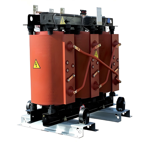
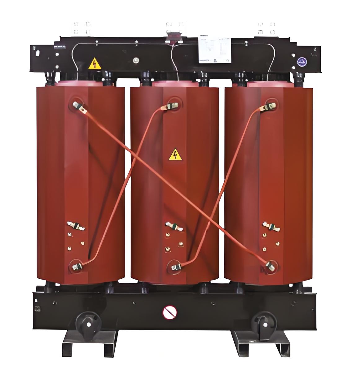
Product at a glance
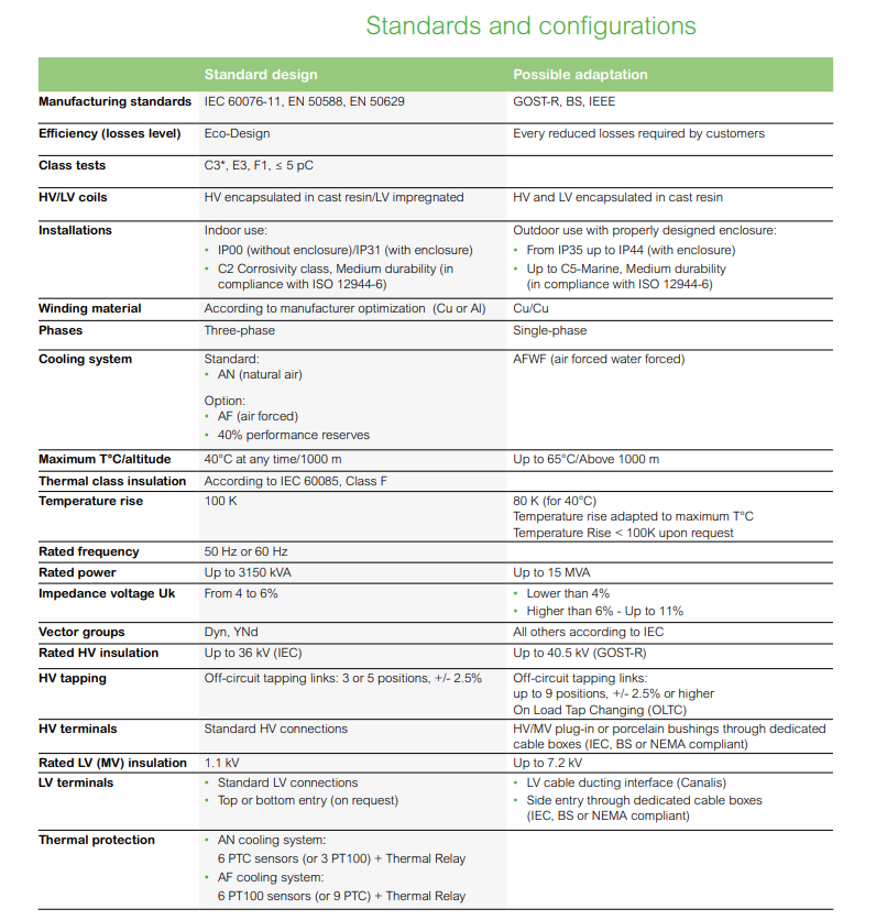
Cast resin, 50 Hz, three-phased distribution transformers with the following characteristics:
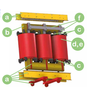
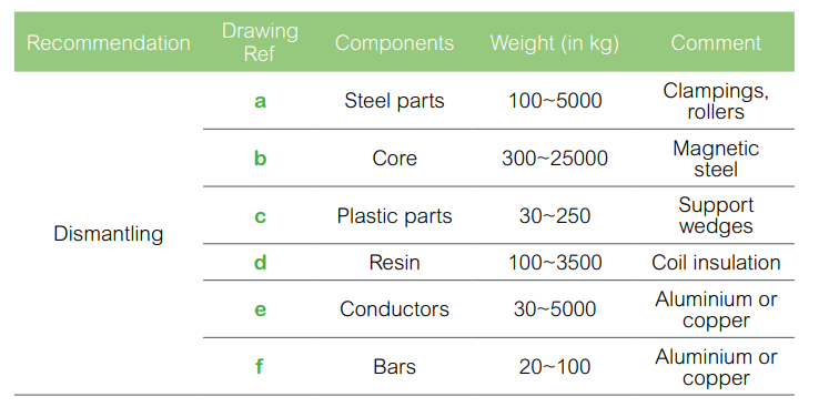
The components of the products
Compliance:
These transformers comply with standards:
Schneider Electric guarantees that its transformers are silicone free and certified:
Trihal
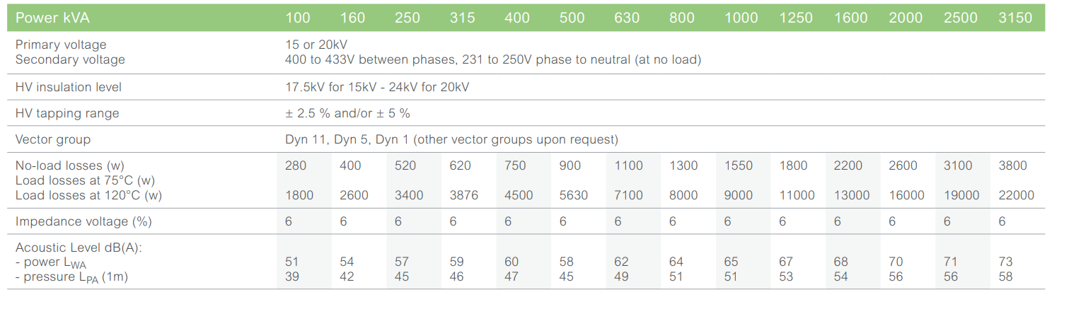
Up to 3150 kVA, 12 kV, losses
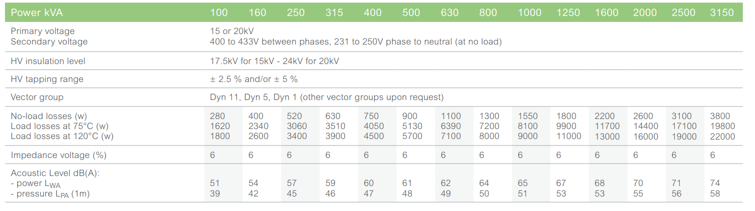
Main electrical characteristics
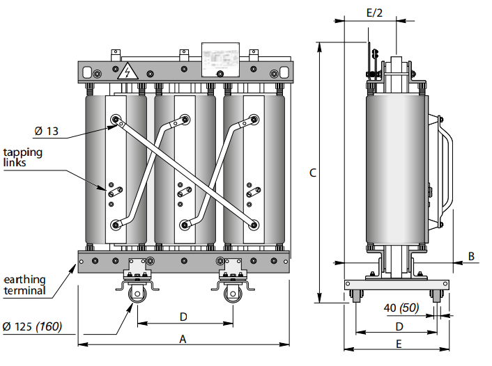
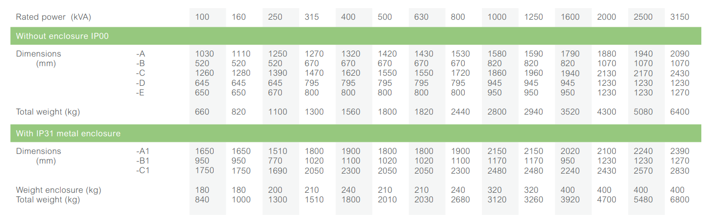
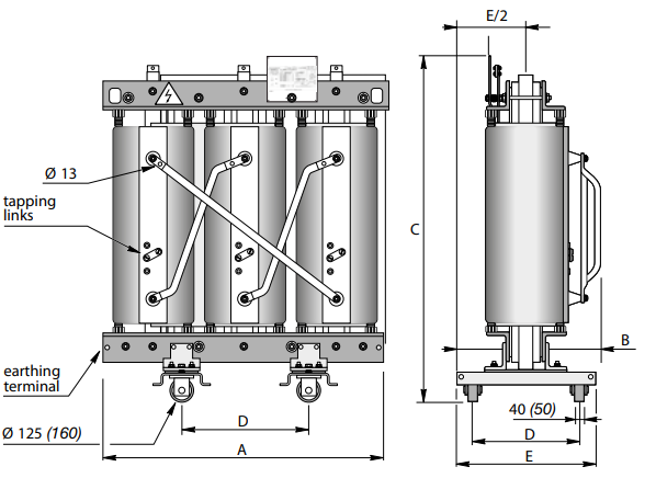
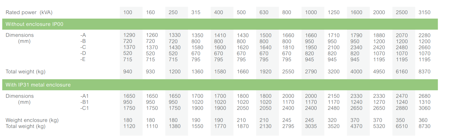
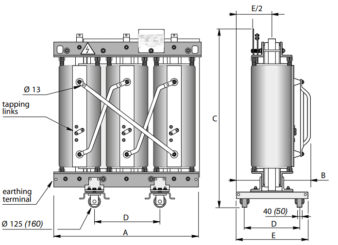
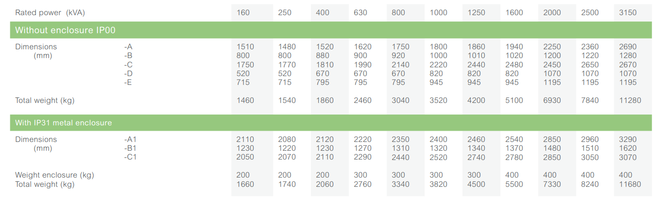
Dimensions* and weights
Without enclosure (IP00)
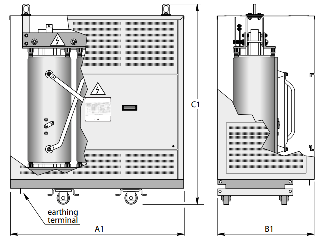
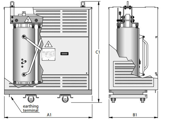
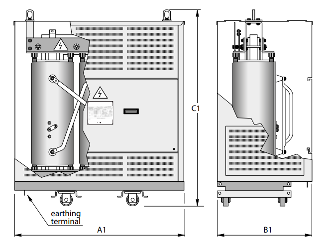
With IP31 metal enclosure
Trihal
Up to 3150 kVA, 17.5 to 24 kV, losses
Main electrical characteristics
Dimensions* and weights
Without enclosure (IP00)
With IP31 metal enclosure
Trihal
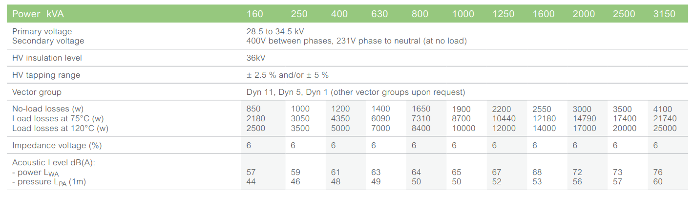
Up to 3150 kVA, 36 kV, losses
Main electrical characteristics
Dimensions* and weights
Without enclosure (IP00)
With IP31 metal enclosure
All available Trihal technical range
Trihal
Options and accessories
High voltage surge arresters
If the installation is likely to be subjected to overvoltage of any kind (atmospheric or switching), the transformer must be protected by phase-to-earth surge arresters, installed directly on the transformer’s HV connection terminals (either at the top or the bottom).
It is essential to install these surge arresters:
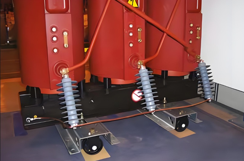
High voltage surge arresters on the lower part
Vibration damping
Roller anti-vibration pads
This accessory, placed under the rollers, avoids vibrations being transmitted from the transformer to its environment.
Damper unit
This device is installed instead of the roller and enables transmission of vibrations to the transformer environment to be attenuated.
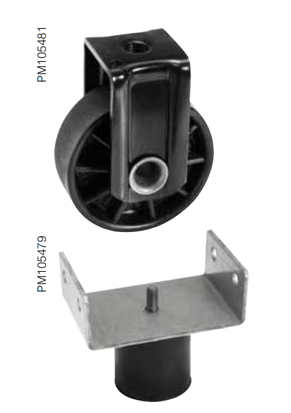
Anti-damping accessories
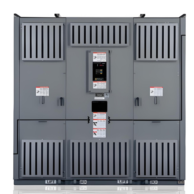
Protective Enclosure
The IP and IK protective indices refer to the following criteria:
IP protection indices
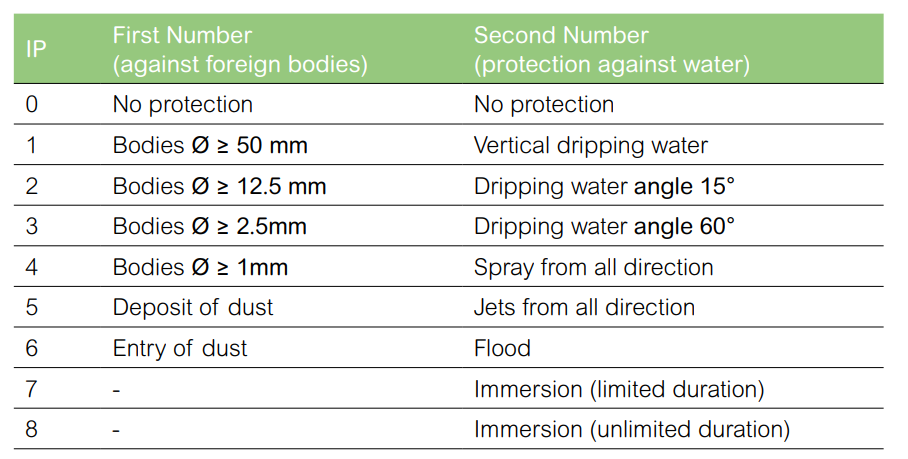
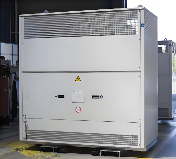
Protective enclosure IP31, IK7