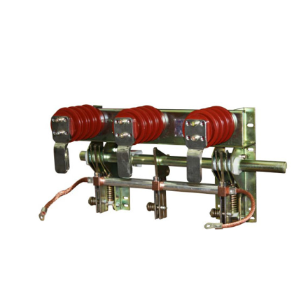
| Brand | ROCKWILL |
| Model NO. | HV Grounding Switch 40.5kV 72.5kV 126kV 252kV 363kV 500kV 800kV |
| Rated voltage | 800kV |
| Series | JW6(8) Series |
The JW6/8 series high-voltage grounding switches feature a three-single-pole configuration integrated with an operating mechanism. Each single pole comprises a base, a pillar insulator, and a conductive rod: the rod is mounted on the base, while the static contact is positioned at the top of the insulator.
Driven by the operating mechanism, the conductive rod rotates upward from the horizontal position via transmission components, latching or inserting into the static contact to achieve switch closure; the opening process reverses this motion.
Streamlined Design & Versatility:The product’s simple, rational structure enables effortless assembly, transportation, installation, and debugging, adapting to diverse field requirements.
High-Performance Conductive Components:Constructed from high-strength alloy profiles, the conductive rods offer excellent electrical conductivity, robust mechanical strength, and lightweight design. Their superior anti-corrosion properties ensure prolonged service life in harsh environments.
| Specifications |
Unit | JW6-40.5 | JW6-72.5 | JW6-126 | JW6-252 | JW8-363 | JW8-550 | JW8-800 | |
|---|---|---|---|---|---|---|---|---|---|
| Model | - | JW6-40.5 | JW6-72.5 | JW6-126 | JW6-252 | JW8-363 | JW8-550 | JW8-800 | |
| Rated voltage | kV | 40.5 | 72.5 | 126 | 252 | 363 | 550 | 800 | |
| Rated frequency | Hz | 50 | 50 | 50 | 50 | 50 | 50 | 50 | |
| 1min power frequency withstand voltage (r.m.s) | kV | 95 | 160 | 230 | 460 | 510 | 740 | 960 | |
| Lightning impulse withstand voltage (peak 1.2/50μs) | kV | 185 | 380 | 550 | 1050 | 1175 | 1675 | 2100 | |
| Rated operating impulse withstand voltage (peak 250/2500μs) | kV | \ | \ | \ | \ | 950 | 1300 | 1550 | |
| Rated short-time withstand current (r.m.s) | kA | 40 | 40 | 40 | 50 | 63 | 63 | 63 | |
| Rated peak withstand current | kA | 100 | 100 | 100 | 125 | 160 | 160 | 170 | |
| Rated short-circuit withstand time | s | 4 | 4 | 3 | 3 | 3 | 3 | 3 | |
| Wiring terminal static mechanical load | Longitudinal | N | 800 | 800 | 1250 | 2000 | 2000 | 4000 | 4000 |
| Horizontal | N | 500 | 500 | 750 | 1500 | 1500 | 2000 | 3000 | |
| Vertical | N | 750 | 750 | 1000 | 1250 | 1500 | 1500 | 2000 | |
| Operational altitude | m | ≤2000 | ≤2000 | ≤2000 | ≤2000 | ≤2000 | ≤1000 | ≤2000 | |
| Operating pollution class | Class | AG5 | AG5 | AG5 | AG5 | AG5 | AG5 | AG3 | |
| Mechanical life | Times | 10K | 10K | 5K | 10K | 5K | 5K | 3K | |
| Radio interference level | uV | ≤500 | ≤500 | ≤500 | ≤500 | ≤500 | ≤500 | ≤2000 | |
| The switching induced current capacity of the grounding switch | Electromagnetic induction current | A | 6 | 6 | 50/100 | 80/160 | 80/400 | 80/400 | 80/400 |
| Electromagnetic induction voltage | kV | 100 | 100 | 0.5/6 | 1.4/15 | 2/35 | 2/35 | 2/35 | |
| Electrostatic induction current | A | 6 | 6 | 0.4/5 | 1.25/10 | 2/35 | 2/50 | 3/50 | |
| Electrostatic induction voltage | kV | 2 | 2 | 3/6 | 5/15 | 8/50 | 8/50 | 12/50 | |
Insulation Resistance Test: Use an insulation resistance tester to measure the insulation resistance of the grounding switch. The insulation resistance value should meet the product standards and relevant electrical codes. Generally, for indoor high-voltage AC grounding switches, the insulation resistance should be in the range of several gigohms or more to ensure good insulation performance during operation and prevent leakage accidents.
Loop Resistance Test: Measure the loop resistance of the grounding switch using a dedicated loop resistance tester to check if the contact points are in good condition. The loop resistance value should fall within the specified range. If the loop resistance is too high, it may cause significant heating when current flows through the grounding switch, affecting its normal operation.
Grounding Performance Check: Ensure that the grounding connection is reliable and that the grounding resistance meets the requirements. If the grounding resistance is too high, it may prevent the current from being effectively discharged to the ground during a fault, thus failing to provide adequate protection for maintenance personnel and equipment.











 Login