| Brand | MV Switchgear Accessories |
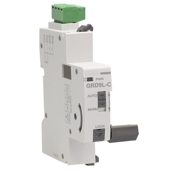
| Model NO. | GRD9L-C Switch Recloser Module |
| Rated voltage | AC220V |
| Rated frequency | 50/60Hz |
| Series | GRD9L-C |
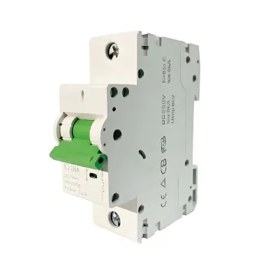
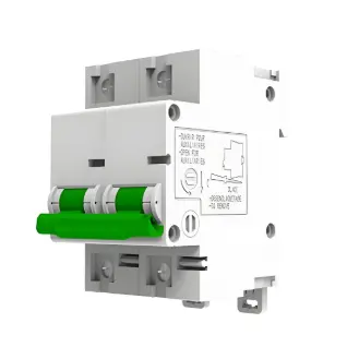
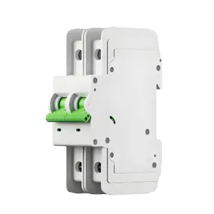
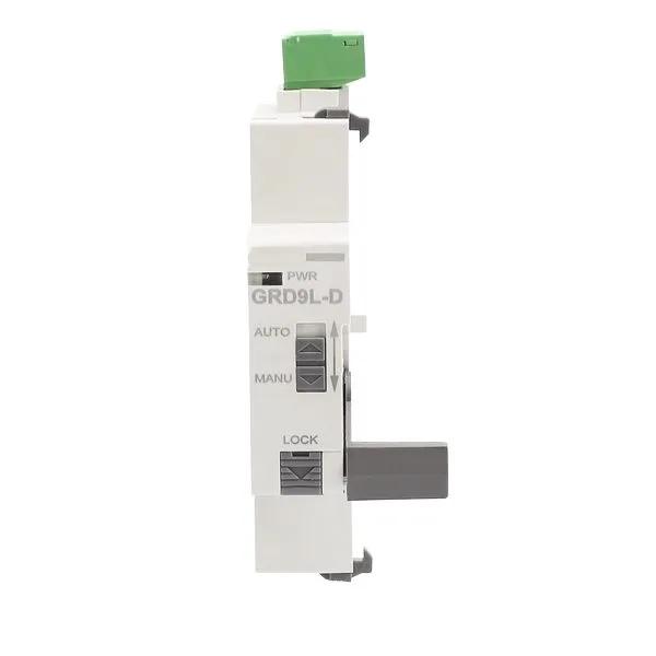
The GRD9L-C automatic recloser can be matched with circuit breakers/leakage protection switches. It controls the closing and tripping of circuit breakers/leakage protection switches via switch signals and also supports remote operation. Featuring both mechanical and electronic locking functions, it is widely applicable in grid terminal lines, new energy circuit management, smart electronic triplets, intelligent furniture, smart factories, and new energy vehicle charging piles.
Feature
It can be matched with MCB/RCCB to remotely close and open MCB/RCCB.
MCB/RCCB controlled by switch, type D has auto reclosing function.
With manual/automatic selector switch.
With mechanical/electronic double locking function.
The shaft transmission mode is more stable and reliable.
Can match other accessories.
Work status is indicated by LED.
1-MODULE.
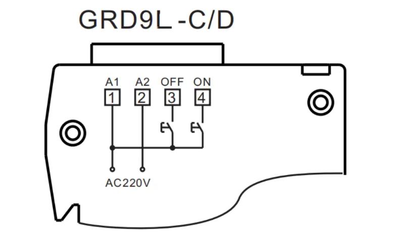
Wiring Diagram
| Type | GRD9L-C |
| Control mode | Controlled by switch |
| Supply terminals | A1-A2 |
| Voltage range | DC12V |
| Power input | DC max.1W(standby) max.20W(action) |
| Voltage range | AC 220V(50-60Hz) |
| Supply voltage tolerance | -10%; + 10% |
| Powerinput | AC max.1VA(standby) max.20VA(action) |
| Supply voltage tolerance | -10%;+10% |
| Supply indication | red LED |
| Action time | ≤1s |
| Auto reclosing times | – |
| Auto reclosing time interval | – |
| Reset the closing times | – |
| Mechanical life | 10000 |
| Electrical life(AC1) | 4000 |
| Operating temperature | -20℃ to +55℃ (-4℉ to 131℉ ) |
| Storage temperature | -35℃ to +75℃ (-22℉ to 158℉ ) |
| Mounting/DIN rail | Din rail EN / IEC 60715 |
| Protection degree | IP20 |
| Operating position | any |
| Overvoltage cathegory | III. |
| Pollution degree | 2 |
| Max.cable size(mm2) | solid wire max. 1X2.5 or 2X1. 5 / with sleeve max.1 X2.5(AWG 12) |
| Dimensions | 82X18X78mm |
| Weight | 80g |
| Combination with accessories | |
| Auxiliary contact | Yes |
| Alarm contact | Yes |
| Shunt release | Yes |
| Under voltage release | Yes |