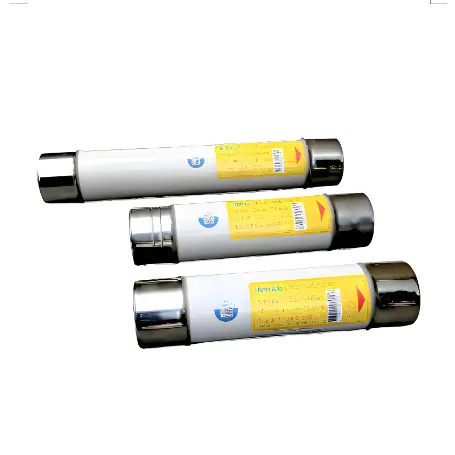
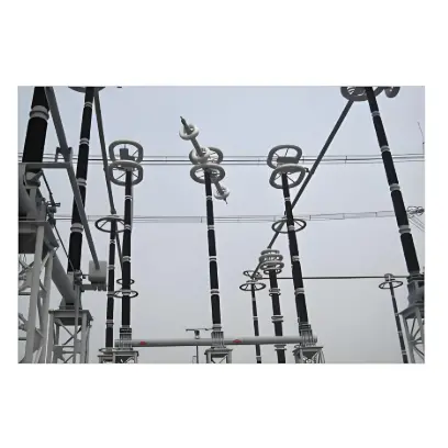
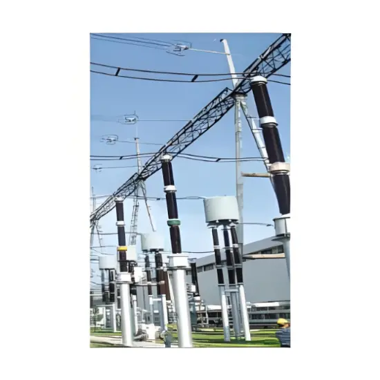
• Product
  • Suppliers
  • Manufacturers
  • Solutions
  • Free tools
  • Knowledges
  • Experts
  • Communities
Search


DNT6-O1J aR Semiconductor Protection AC High Speed Fuse Link

  • DNT6-O1J aR Semiconductor Protection AC High Speed Fuse Link
  • DNT6-O1J aR Semiconductor Protection AC High Speed Fuse Link
  • DNT6-O1J aR Semiconductor Protection AC High Speed Fuse Link

Key attributes

Brand Switchgear parts
Model NO. DNT6-O1J aR Semiconductor Protection AC High Speed Fuse Link
Rated voltage AC 1300V
Rated normal current 1250-3900A
Breaking capacity 100kA
Series DNT6-O1J

Product descriptions from the supplier

Description

What are the common current and voltage ratings for semiconductor fuses used in various applications?

 The current and voltage ratings of semiconductor fuses can vary widely depending on their intended application. These ratings are critical for ensuring that the fuse can effectively protect electronic components by interrupting overcurrent conditions without prematurely blowing under normal operating conditions.

Here’s a general overview of common ratings for semiconductor fuses in various applications:

Consumer Electronics

Voltage Ratings: Typically range from 5V for small devices (like smartphones and tablets) up to 250V for larger household appliances.

Current Ratings: Can be as low as a few milliamperes (mA) for very sensitive circuits and up to several amperes (A) for larger appliances.

Industrial Equipment

Voltage Ratings: Industrial fuses can vary significantly, often ranging from 250V to 600V in many applications. For specialized equipment, the voltage rating can be much higher.

Current Ratings: Commonly range from a few amperes to several hundred amperes, depending on the power requirements of the equipment.

Data Centers and Telecommunications

Voltage Ratings: Typically in the range of 48V for telecommunications equipment to 120V or 240V in data centers, and sometimes higher for large-scale installations.

Current Ratings: Can range from under 1A for small devices to 100A or more for large power distribution units.

Automotive and Electric Vehicles (EVs)

Voltage Ratings: For traditional automotive applications, 12V or 24V is common. In electric vehicles, high-voltage systems can operate at 400V to 800V or even higher.

Current Ratings: Varies widely; small fuses in a vehicle’s electronic system might be rated for only a few amperes, while EV battery fuses could be rated for several hundred amperes due to the high power requirements.

Renewable Energy Systems (Solar, Wind)

Voltage Ratings: In solar panel arrays, common ratings might be 600V, 1000V, or 1500V. Wind turbines might use fuses rated for several kilovolts, depending on the system design.

Current Ratings: Typically in the range of 10A to 250A, but this can be higher for larger installations or different configurations.aR Semiconductor Protection

Medical Equipment

Voltage Ratings: Typically range from 120V to 240V for equipment used in areas with standard electrical outlets. Specialized equipment might require different ratings.

Current Ratings: Generally lower, often ranging from less than 1A to around 20A, reflecting the lower power requirements and the emphasis on precision and safety.

General Considerations

Application-Specific Needs: The appropriate rating for a semiconductor fuse depends on the specific electrical and thermal characteristics of the application.aR Semiconductor Protection

Safety Margins: Fuses are usually selected with a certain margin above the normal operating current to prevent nuisance tripping but still provide reliable protection against overcurrents.

Environmental Factors: The operating environment (such as temperature, humidity, and potential exposure to chemicals or mechanical stress) can also influence the selection of fuses.

It’s important to note that these are general ranges and the actual requirements for a specific application can vary. Engineers and designers typically refer to detailed specifications and standards when selecting fuses for a particular use case.

Basic parameters of fuse links

Product model size Rated voltage          V Rated current         A Rated breaking  capacity    kA
DNT6-01J-1250 6 AC 1300 1250 100
DNT6-01J-1400 1400
DNT6-01J-1500 1500
DNT6-01J-1600 1600
DNT6-01J-1800 1800
DNT6-01J-2000 2000
DNT6-01J-2300 2300
DNT6-01J-2500 2500
DNT6-01J-2800 2800
DNT6-01J-3000 3000
DNT6-01J-3200 3200
DNT6-01J-3600 3600
DNT6-01J-3900 3900
Know your supplier
Online store
On-time delivery rate
Response time
100.0%
≤4h
Company overview
Workplace: 1000m² Total staff: Highest Annual Export(usD): 300000000
Workplace: 1000m²
Total staff:
Highest Annual Export(usD): 300000000
Services
Business Type: Sales
Main Categories: Low Voltage Electrical Apparatus/Instrument meters/Production equipment/Tester/High Voltage Electrical Apparatus/Electrical fittings/Equipment Parts
Whole life care manager
Whole-life care management services for equipment procurement, use, maintenance, and after-sales, ensuring safe operation of electrical equipment, continuous control, and worry-free electricity consumption.
The equipment supplier has passed platform qualification certification and technical evaluation, ensuring compliance, professionalism, and reliability from the source.

Related Products

Related Knowledges

  • Impact of DC Bias in Transformers at Renewable Energy Stations Near UHVDC Grounding Electrodes
    Impact of DC Bias in Transformers at Renewable Energy Stations Near UHVDC Grounding ElectrodesWhen the grounding electrode of an Ultra-High-Voltage Direct Current (UHVDC) transmission system is located close to a renewable energy power station, the return current flowing through the earth can cause a rise in ground potential around the electrode area. This ground potential rise leads to a shift in the neutral-point potential of nearby power transformers, inducing DC bias (or DC offset) in their
    01/15/2026
  • HECI GCB for Generators – Fast SF6 Circuit Breaker
    1.Definition and Function1.1 Role of the Generator Circuit BreakerThe Generator Circuit Breaker (GCB) is a controllable disconnect point located between the generator and the step-up transformer, serving as an interface between the generator and the power grid. Its primary functions include isolating generator-side faults and enabling operational control during generator synchronization and grid connection. The operating principle of a GCB is not significantly different from that of a standard c
    01/06/2026
  • Distribution Equipment Transformer Testing, Inspection, and Maintenance
    1.Transformer Maintenance and Inspection Open the low-voltage (LV) circuit breaker of the transformer under maintenance, remove the control power fuse, and hang a “Do Not Close” warning sign on the switch handle. Open the high-voltage (HV) circuit breaker of the transformer under maintenance, close the grounding switch, fully discharge the transformer, lock the HV switchgear, and hang a “Do Not Close” warning sign on the switch handle. For dry-type transformer maintenance: first clean the porcel
    12/25/2025
  • How to Test Insulation Resistance of Distribution Transformers
    In practical work, insulation resistance of distribution transformers is generally measured twice: the insulation resistance between thehigh-voltage (HV) windingand thelow-voltage (LV) winding plus the transformer tank, and the insulation resistance between theLV windingand theHV winding plus the transformer tank.If both measurements yield acceptable values, it indicates that the insulation among the HV winding, LV winding, and transformer tank is qualified. If either measurement fails, pairwise
    12/25/2025
  • Design Principles for Pole-Mounted Distribution Transformers
    Design Principles for Pole-Mounted Distribution Transformers(1) Location and Layout PrinciplesPole-mounted transformer platforms should be located near the load center or close to critical loads, following the principle of “small capacity, multiple locations” to facilitate equipment replacement and maintenance. For residential power supply, three-phase transformers may be installed nearby based on current demand and future growth projections.(2) Capacity Selection for Three-Phase Pole-Mounted Tr
    12/25/2025
  • Transformer Noise Control Solutions for Different Installations
    1.Noise Mitigation for Ground-Level Independent Transformer RoomsMitigation Strategy:First, conduct a power-off inspection and maintenance of the transformer, including replacing aged insulating oil, checking and tightening all fasteners, and cleaning dust from the unit.Second, reinforce the transformer foundation or install vibration isolation devices—such as rubber pads or spring isolators—selected based on the severity of vibration.Finally, strengthen sound insulation at weak points of the ro
    12/25/2025
Haven't found the right supplier yet? Let matching verified suppliers find you. Get Quotation Now
Haven't found the right supplier yet? Let matching verified suppliers find you.
Get Quotation Now
Send inquiry
+86
Click to upload file

IEE Business will not sell or share your personal information.

Download
Get the IEE Business Application
Use the IEE-Business app to find equipment, obtain solutions, connect with experts, and participate in industry collaboration anytime, anywhere—fully supporting the development of your power projects and business.