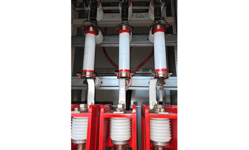
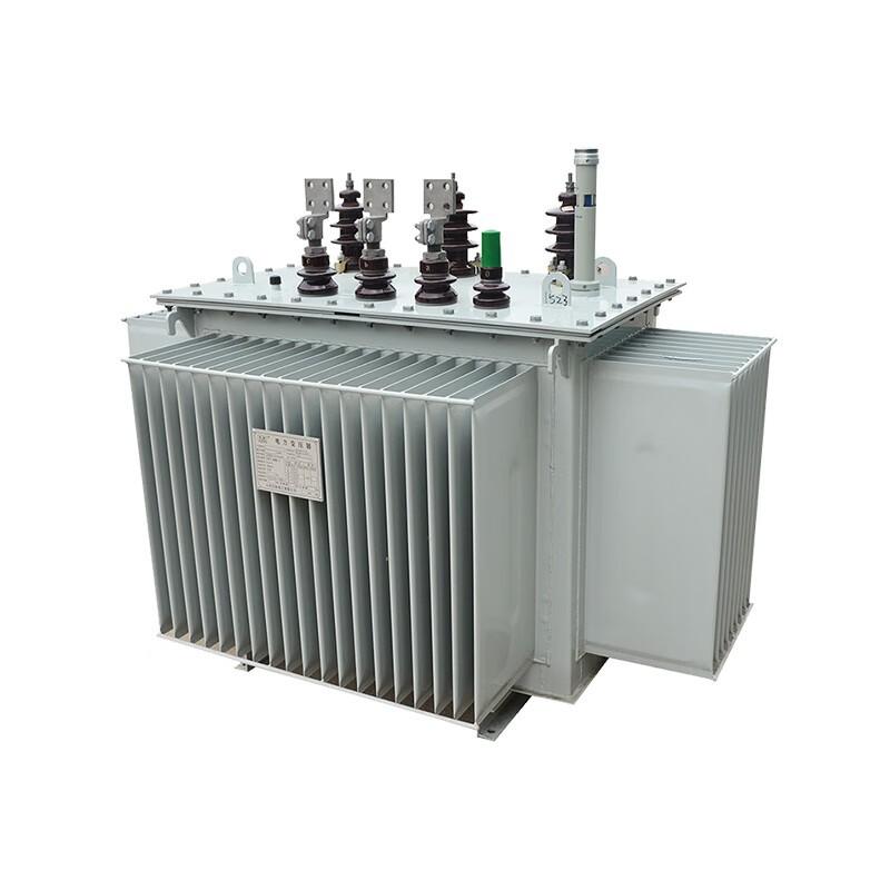
I. Fuse Structure and Root Cause Analysis
Slow Fuse Blowing:
From the design principle of fuses, when a large fault current passes through the fuse element, due to the metal effect (certain refractory metals become fusible under specific alloy conditions), the fuse first melts at the soldered tin ball. The arc then rapidly vaporizes the entire fuse element. The resulting arc is quickly extinguished by quartz sand.
However, due to harsh operating environments, the fuse element may age under the combined effects of gravity and thermal accumulation. This can lead to fuse fracture even under normal load current. Since the fuse blows under normal current, the melting process is slow. As the fuse resistance gradually increases, the phase voltage amplitude drops, potentially causing maloperation of associated protection relays.
Impact of PT Slow Fuse Blow:
If the high-voltage side PT fuse does not fully clear within the specified time, the resistance of the fuse tube increases continuously, causing a steady decrease in the secondary output voltage of the voltage transformer (TV).
II. Hazards of PT Slow Fuse Blow
Excitation system initiates field forcing, leading to over-excitation and overvoltage protection activation.
Maloperation of stator ground fault protection.
Generator and turbine overloading, which may cause equipment damage in severe cases.

III. Root Cause Analysis
Different materials used in the primary plug-in contacts of the output voltage transformer cause oxidation layers and poor contact; loose connection bolts increase temperature rise on the fuse.
High ambient temperature around the PT fuse. The fuse element is made of low-melting-point metal and is very thin—mechanical vibration alone may cause breakage.
Poor-quality PT fuses are prone to degradation or premature failure during operation.
Transient overvoltages from sudden breaker closing or intermittent arc grounding may cause ferroresonance, leading to primary and secondary fuse blowing in voltage transformers.
Low-frequency saturation current can cause primary and secondary fuse blowing in voltage transformers.
Reduced insulation or short circuits in primary/secondary windings of the voltage transformer, or degraded insulation in the harmonic suppressor, may cause fuse blowing.
Single-phase-to-ground faults may lead to voltage transformer burnout.
Generators are typically grounded via an arc suppression coil at the neutral point. However, this configuration can amplify neutral point displacement voltage, causing one or two phases to sustain voltages significantly above normal for extended periods, leading to PT fuse blowing.
IV. Preventive Measures
For oxidation and poor contact at primary plug contacts due to material mismatch, perform contact surface polishing during maintenance and apply conductive grease.
To address unstable fuse quality, replace high-voltage primary fuses periodically according to the equipment maintenance schedule. Contact surfaces must be de-oxidized and coated with conductive grease.
For systems with high vibration: after pushing the PT trolley to the service position, verify all conductive connections are secure and free of looseness. If necessary, withdraw the trolley and tighten bolts. During unit outages with no work on the generator primary or generator outlet PT circuits, keep the generator outlet PT in standby (do not disconnect it). Only open the secondary circuit breaker. This minimizes frequent insertion/removal, preventing fuse drop, mechanical damage, or poor contact with socket spring clips—reducing the likelihood of high-voltage fuse failure. (Before placing the generator in hot standby, operating personnel must verify the integrity of the primary PT fuse.)
During single-phase-to-ground faults, if the generator operates at rated frequency, transient overvoltage on healthy phases can reach up to 2.6 times the rated phase voltage. Therefore, generator outlet voltage transformers must be selected to withstand these overvoltages:
Steady-state overvoltage withstand ≥ line voltage
Transient overvoltage withstand ≥ 2.6 × rated phase voltage
PT fuse selection must not only isolate internal transformer short circuits but also protect against overvoltage conditions such as voltage rise and ferroresonance.
Primary harmonic suppression: Install a grounding voltage transformer between the primary neutral point of the VT and ground. This effectively suppresses or eliminates overvoltage in the primary winding and prevents ferroresonance and transformer burnout.
Secondary harmonic suppression: Install a damping device (secondary harmonic suppressor) across the open delta of the VT’s residual winding. Modern microprocessor-based harmonic suppressors detect incipient resonance and instantly connect a damping resistor to eliminate ferroresonance. When the generator neutral is grounded via an arc suppression coil (whose inductance is much smaller than the VT’s magnetizing inductance), ferroresonance overvoltage is effectively prevented. Therefore, ferroresonance need not be considered in PT fuse blow analysis.
Coordinate with the excitation system manufacturer to ensure the excitation regulator includes logic to detect slow blowing of PT primary fuses (considering single-phase, two-phase, and three-phase fuse failure scenarios) and secondary circuit breaks. Upon detecting a PT break, the main excitation channel should automatically switch from AVR mode to FCR mode, or switch to the backup channel. Adjust the threshold settings in the PT break detection logic to reduce false triggering of field forcing due to poor PT circuit contact, thereby improving system sensitivity and reliability.
V. Methods for Detecting PT Slow Fuse Blow
Criterion 1: Introduction of Zero-Sequence and Negative-Sequence Voltage
a) Zero-Sequence Voltage Method
Monitor the open-delta voltage on the PT secondary side. Compare the generator terminal zero-sequence voltage with the neutral point zero-sequence voltage. If the absolute difference exceeds a preset threshold, a PT slow fuse blow is indicated. In this case, the stator negative-sequence current criterion must be blocked.
b) Negative-Sequence Voltage Method
The excitation system only measures generator terminal voltage, not neutral point voltage, making the zero-sequence method inapplicable. Instead, decompose the PT secondary voltage to extract the negative-sequence component. If the negative-sequence voltage exceeds a set threshold, a PT primary fuse slow blow is detected. The stator negative-sequence current criterion must also be blocked.
Criterion 2:
UAB – Uab > 5V
UBC – Ubc > 5V
UCA – Uca > 5V
Key Point: Use zero-sequence, negative-sequence, and voltage comparison methods. Never use positive-sequence voltage (used by protection relays) to detect primary PT fuse failure, because the broken phase still induces voltage (not zero), which may not satisfy positive-sequence criteria.
A primary PT fuse break causes induced imbalance in the secondary EMF, resulting in voltage at the open delta and triggering a zero-sequence alarm. This phenomenon does not occur with a secondary fuse blow—this is the primary distinguishing criterion between primary and secondary fuse failures.
A primary PT fuse break reduces the secondary induced voltage (because the other two phases still produce flux in the core), so the corresponding secondary phase voltage decreases. In contrast, a secondary fuse break removes the winding from the circuit, causing the phase voltage to drop to zero.


