• Product
  • Suppliers
  • Manufacturers
  • Solutions
  • Free tools
  • Knowledges
  • Experts
  • Communities
Search


Compact Arrangement High voltage disconnect switch-363kV 420kV 550kV

  • Compact Arrangement High voltage disconnect switch-363kV 420kV 550kV

Key attributes

Brand ROCKWILL
Series RDS
Rated voltage 363kV-550kV
Rated current 3150-5000A
Rated short-time withstand current 50/63kA
Rated frequency 50 / 60Hz
Description
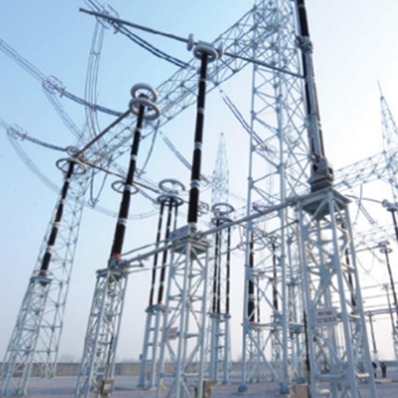
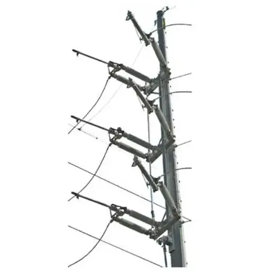
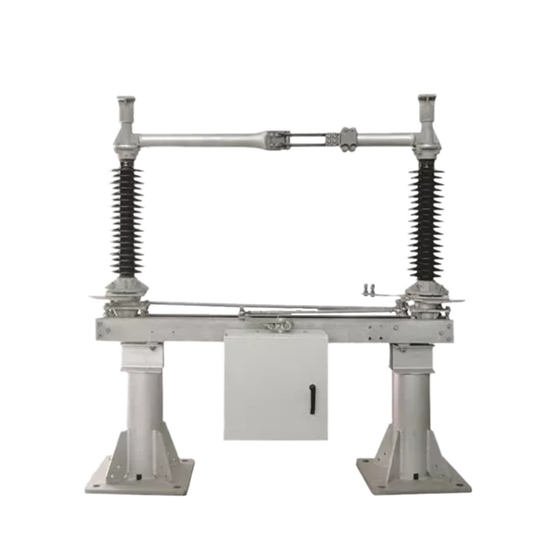
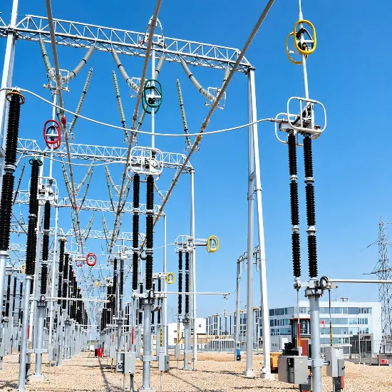
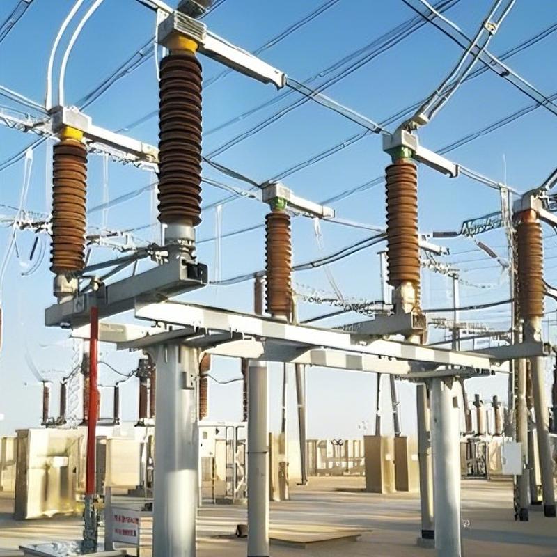
The RDS series outdoor disconnector is designed for 363 kV, 420 kV, and 550 kV three-phase AC transmission systems. It provides visible isolation for equipment maintenance, performs no-load line switching, and is capable of switching capacitive and inductive currents when equipped with arcing contacts.

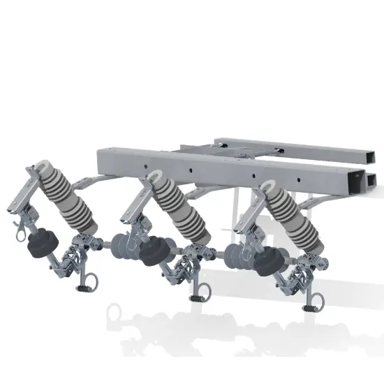
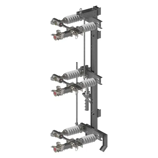
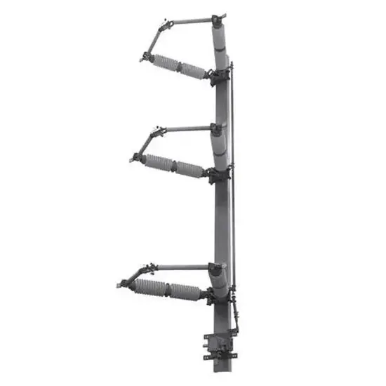
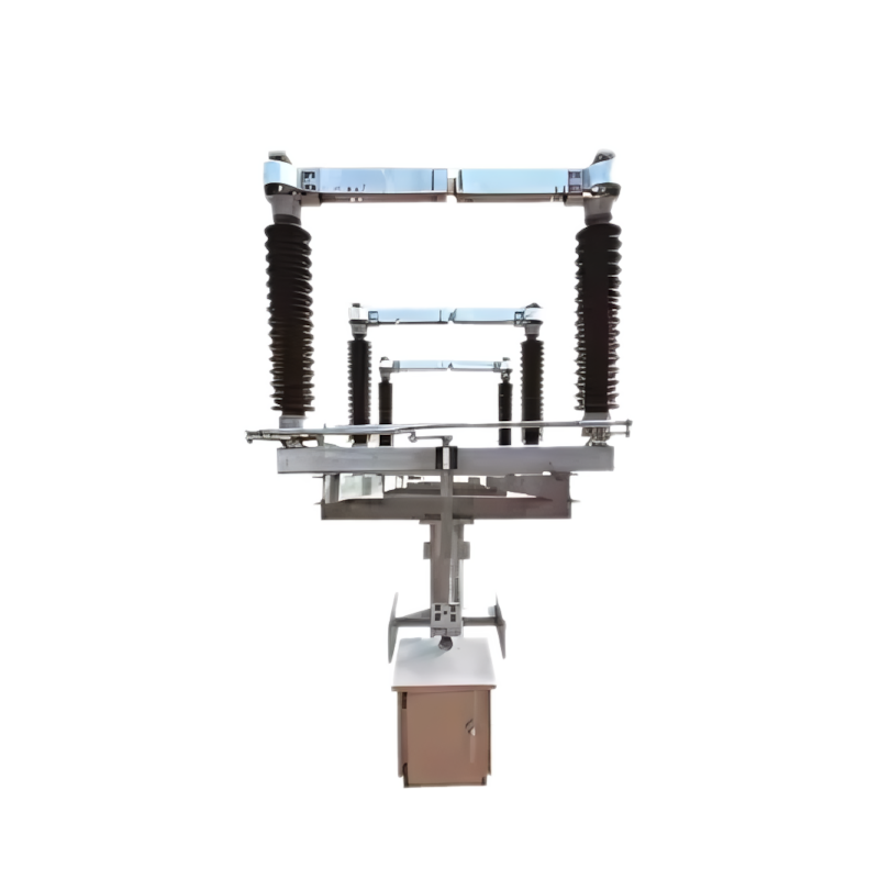
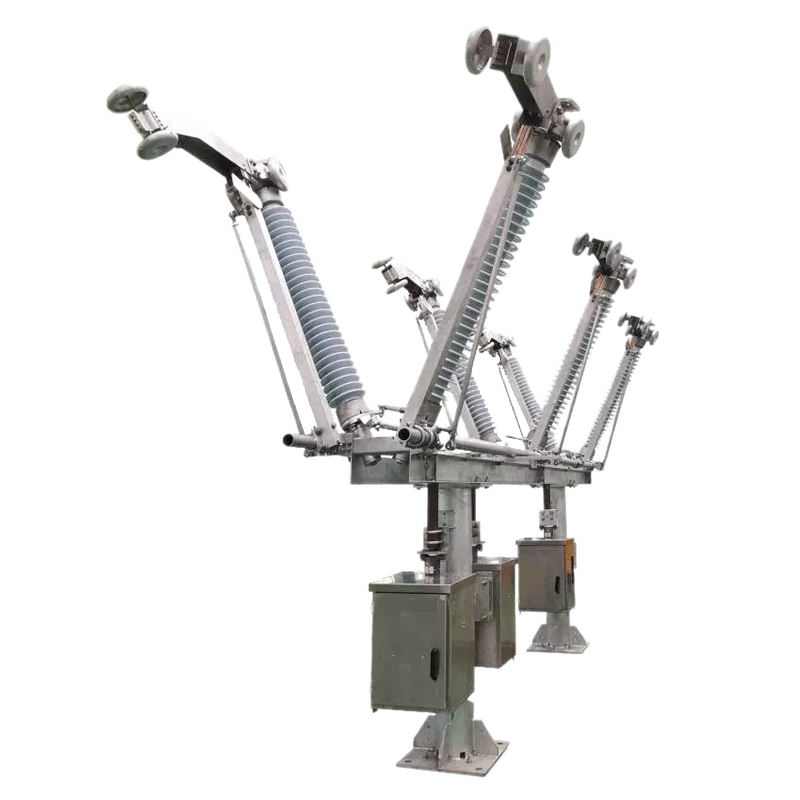
The disconnector adopts a single-post vertical telescopic structure with a forceps-type contact. The conductive arm extends vertically upward and grips the busbar contact from below, forming a vertical insulating break after opening. This configuration mounts directly under the overhead busbar without additional support structures, requiring minimal switchyard space.

The SRCJ2 motor actuator drives each phase independently with three-pole linkage capability. The earthing switch uses a single-arm standing openable structure at 363 kV and above, with a two-step opening and closing motion. The earthing rod rotates vertically, extends upward, and plugs automatically into a star-shaped contact for reliable high-current earthing.

Key Features

  • Bus-mounted vertical telescopic design:Single-post structure mounts directly under the overhead busbar without additional support columns, saving switchyard space and reducing foundation work compared to conventional two-post or three-post configurations
  • Forceps-type self-locking contact:External stainless steel spring maintains constant contact pressure independent of current flow; contact clamping force increases automatically under short-circuit conditions due to magnetic pinch effect, preventing contact lift-off
  • Sealed anti-corrosion construction:Contact base welded to the upper guide tube prevents water penetration into the clamping head; draw rod connection is uniquely sealed to eliminate water accumulation inside the conductive arm, preventing internal corrosion and ice-induced mechanism jamming in winter
  • Two-step earthing switch:Earthing rod rotates vertically, extends upward, and plugs into a star-shaped fixed contact in two distinct motions: vertical rotation followed by automatic insertion, ensuring reliable plug-type contact capable of withstanding heavy short-circuit currents
  • Arc contact for current switching: Optional arcing contacts installed on the main and fixed contacts enable the disconnector to switch capacitive line-charging currents and inductive transformer magnetizing currents within defined limits, extending functionality beyond basic isolation
  • Flexible shunt current path: Current transfers through the foldable joint via a flexible soft connection without sliding contacts, eliminating contact wear at the hinge and ensuring stable resistance across the full mechanical life
Technical Parameters

Item Unit 363 kV 420 kV 550 kV
Rated voltage (Um) kV 363 420 550
Rated frequency Hz 50 / 60 50 / 60 50 / 60
Rated current A 3,150, 4,000, 5,000 3,150, 4,000 3,150, 4,000, 5,000
Rated short-time withstand current kA 50 / 63 50 / 63 63
Rated short-circuit withstand duration s 3 3 3
Rated peak withstand current kA peak 125 / 160 125 / 160 160
Rated power-frequency withstand voltage (1 min), phase to earth kV 510 520 620
Rated power-frequency withstand voltage (1 min), across isolating distance kV 510 + 210 520 + 240 620 + 315
Rated lightning impulse withstand voltage, phase to earth kV peak 1,175 1,425 1,550
Rated lightning impulse withstand voltage, across isolating distance kV peak 1,175 + 295 1,425 + 339 1,550 + 445
Rated switching impulse withstand voltage, phase to earth kV peak 950 1,050 1,175
Rated switching impulse withstand voltage, across isolating distance kV peak 950 + 210 1,050 + 240 1,175 + 315
Mechanical endurance operations 10,000 10,000 10,000
Terminal static load (longitudinal / transverse / vertical) N 4,000 / 1,600 / 1,500 4,000 / 2,000 / 1,500 5,000 / 2,500 / 2,000
Bus-transfer current switching capability A / V 2,400 / 435 2,400 / 435 2,400 / 435
Creepage distance mm 9,080 / 11,250 10,500 / 13,020 13,750 / 17,050
Operating altitude m ≤ 2,000 ≤ 2,000 ≤ 2,000
Pollution level per IEC 60815 class IV (very heavy) IV (very heavy) IV (very heavy)
Radio interference voltage (RIV) µV ≤ 500 ≤ 500 ≤ 500

 Operating Mechanism

Item 363 kV 420 kV 550 kV
Disconnector actuator SRCJ2 motor (single-pole, three-pole linkage supported) SRCJ2 motor (single-pole, three-pole linkage supported) SRCJ2 motor (single-pole, three-pole linkage supported)
Earthing switch actuator CS11 manual (three-pole linkage) CS11 manual (three-pole linkage) CS11 manual (three-pole linkage)
Motor voltage AC 380 V / DC 220 V AC 380 V / DC 220 V AC 380 V / DC 220 V
Control voltage AC 220 V / DC 220 V / DC 110 V AC 220 V / DC 220 V / DC 110 V AC 220 V / DC 220 V / DC 110 V
Opening / closing time 16 s ± 1 s 16 s ± 1 s 18 s ± 1 s

Application Scenarios

  • 550 kV transmission substations:Busbar isolation and line disconnection in EHV transmission grids
  • 363 kV and 420 kV hybrid switchyards:Direct bus-mounted isolation where space is limited
  • Coastal and industrial substations:Anti-corrosion sealed construction ideal for high-humidity, salt-fog, and chemically aggressive environments
  • Cold-climate substations:Sealed water-proof design and ice-resistant mechanism ensure reliable operation in freezing conditions where conventional disconnectors may jam
  • EHV bus coupler and busbar selector bays:Vertical telescopic disconnector serving as busbar selector; two units can share a common fixed contact to save space

Order Information

When ordering, specify:

  • Product model and rated voltage
  • Rated current and rated short-time withstand current
  • Arcing contact requirement (with or without)
  • Earthing switch configuration (none, left, or right)
  • Busbar height and configuration
  • Upper busbar type (tubular or strain)
  • Motor voltage and control voltage
  • Number of auxiliary switch contacts
  • Installation method
  • Altitude and pollution level (if different from standard)

Documentation Resource Library High voltage disconnect switch

Restricted
12 to 550kV Center Side Break Disconnect Switch Installation and Instruction Manuals 12 to 550kV Center Side Break Disconnect Switch Installation and Instruction Manuals
Installation Manual
English
PDF
Restricted
252 to 1100kV Double End Break Disconnect Switch Installation and Instruction Manuals 252 to 1100kV Double End Break Disconnect Switch Installation and Instruction Manuals
Installation Manual
English
PDF
Public.
Rockwill Electric Group Profile Rockwill Electric Group Profile
Brochure
English

Frequently asked questions

It adopts a single-post vertical telescopic structure equipped with forceps-type contacts. The conductive arm extends vertically upward and grips the busbar contact from below, forming a vertical insulating break after opening. It can be directly mounted under the overhead busbar without additional support structures.

The earthing switch for 363 kV and above ratings adopts a single-arm standing openable structure with two-step opening and closing motion. The earthing rod rotates vertically and extends upward, then automatically inserts into the star-shaped fixed contact. The two-step action ensures reliable plug-type contact to withstand high short-circuit currents for dependable earthing.

It is fitted with the SRCJ2 motor actuator. Each phase can be driven independently while retaining three-pole linkage capability.

Know your supplier

Online store
On-time delivery rate
Response time
100.0%
≤4h
Company overview
Workplace: 108000m² Total staff: 700+ Highest Annual Export(usD): 150000000
Services
Business Type: Design/Manufacture/Sales
Main Categories: Medium and High Voltage Switchgear/Power and Distribution Transformers/Instrument Transformers and Sensors/Lightning Protection and Electrical Insulation/Substations and E-Houses/Electrical Panel and Controlgear
Send inquiry
+86
Click to upload file
Download
Get the IEE Business Application
Use the IEE-Business app to find equipment, obtain solutions, connect with experts, and participate in industry collaboration anytime, anywhere—fully supporting the development of your power projects and business.
Login
or continue with
New here?
Register