• Product
  • Suppliers
  • Manufacturers
  • Solutions
  • Free tools
  • Knowledges
  • Experts
  • Communities
Search


252 to 1100kV Double End Break Disconnect Switch Installation and Instruction Manuals
Installation Manual · ROCKWILL

252 to 1100kV Double End Break Disconnect Switch Installation and Instruction Manuals

252‑1100 kV double‑end‑break disconnect switch, motor‑manual dual‑operator, Rapid‑Set clevis linkage system, multi‑cycle maintenance scheme, for high‑voltage substation open‑air switch‑yard applications.

Updated2026.09
LanguageEnglish
FilePDF · 2.7 MB
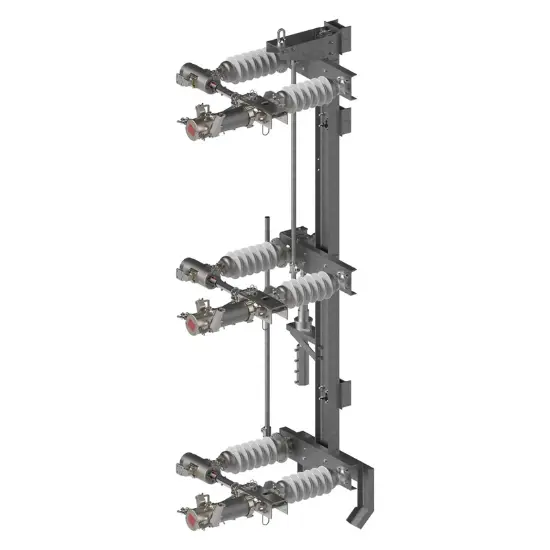
252 to 1100kV Double End Break Disconnect SwitchInstallation and Instruction Manuals

Document description

This is OEM installation‑operation‑maintenance manual for high‑voltage double‑end‑break disconnect switch, complying with prevailing IEC high‑voltage switch‑gear standards.

This document covers goods receiving‑inspection, storage requirements, step‑by‑step field assembly, insulator plumb‑alignment, contact‑engagement tuning, special Rapid‑Set clevis linkage adjustment procedure, arcing‑horn setting, inter‑phase synchronisation tuning, periodic inspection‑maintenance schedules, warranty terms and liability clauses.

It provides graphic‑aided field‑tuning guidance for both traditional and new‑style linkage assemblies, defines qualification requirements for on‑site working staff and forbidden modification rules for equipment. Contact us for complete drawing packages and compliance check‑lists.

Related Products

Frequently asked questions

Any disassembly, alteration or on‑site repair shall obtain manufacturer written approval in advance; unauthorised modification will void product limited‑warranty. Equipment failure event must be notified in writing within stipulated time window. Please contact us for warranty‑clause‑interpretation‑support.

Patrol inspection is visual online check at six‑month intervals; routine maintenance requires de‑energized work every five years including contact cleaning and grease renewal; periodic overhaul executes deeper full‑scope disassembly‑check every ten years. All maintenance activities must be carried out by qualified technical staff. Please contact us for maintenance‑schedule‑template.

Retain factory match‑marks for hinge and blade assembly; use jack‑screws to correct verticality and concentric rotation, control insulator wobble within allowable tolerance. Re‑verify alignment after conductor installation, as conductor weight may shift insulator posture. Please contact us for insulator‑alignment‑checklist.

WhatsApp
Send inquiry
+86
Click to upload file
Download
Get the IEE Business Application
Use the IEE-Business app to find equipment, obtain solutions, connect with experts, and participate in industry collaboration anytime, anywhere—fully supporting the development of your power projects and business.
Login
or continue with
New here?
Register