• Product
  • Suppliers
  • Manufacturers
  • Solutions
  • Free tools
  • Knowledges
  • Experts
  • Communities
Search


12 to 800kV Center Vee Center Break Disconnect Switch Installation and Instruction Manuals
Installation Manual · ROCKWILL

12 to 800kV Center Vee Center Break Disconnect Switch Installation and Instruction Manuals

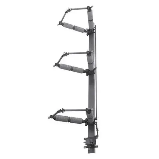
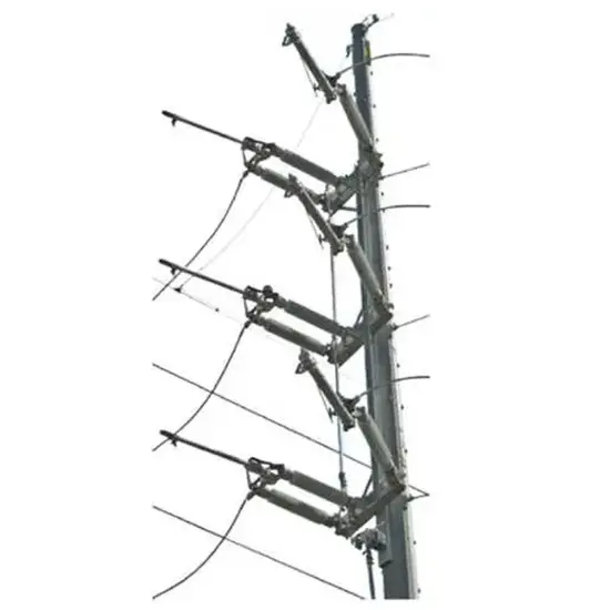
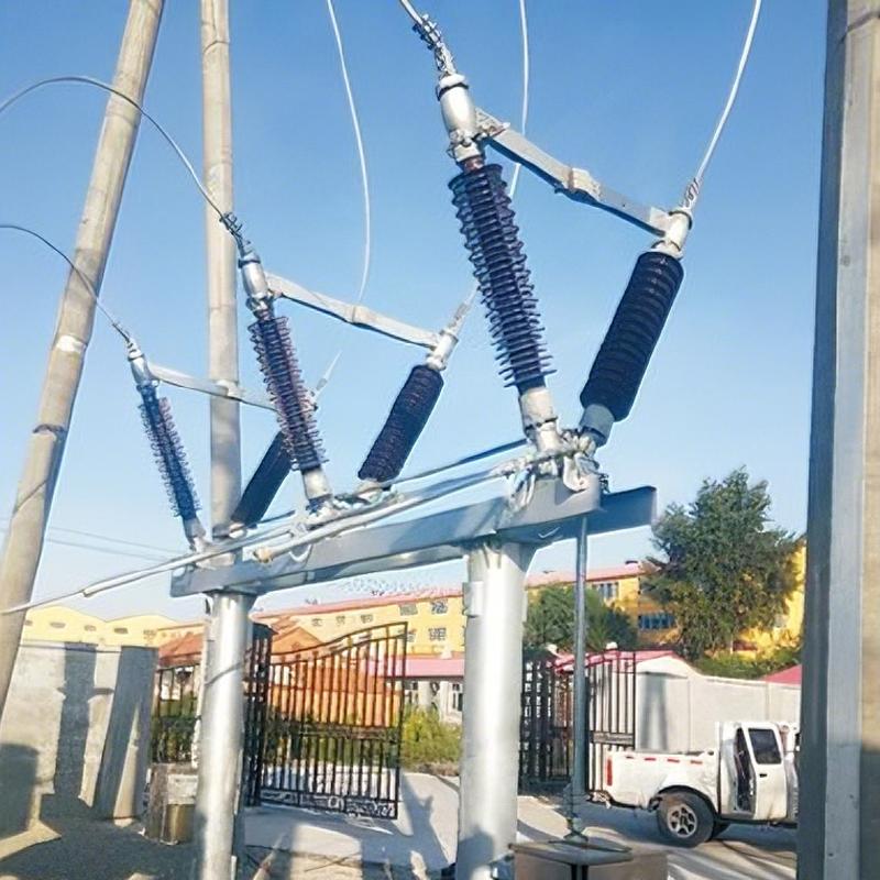
40.5‑145 kV aluminum center‑break V‑type disconnect switch, spring‑/weight‑counterbalanced, Rapid‑Set clevis linkage, motor‑manual dual‑operator, wide ambient‑temperature range, for outdoor substation switch‑yard applications.

Updated2026.09
LanguageEnglish
FilePDF · 1.9 MB
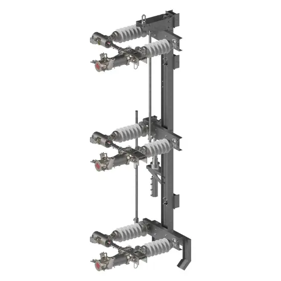
12 to 800kV Center Vee Center Break Disconnect SwitchInstallation and Instruction Manuals

Document description

This is OEM installation‑operation‑maintenance manual for aluminium center‑break V‑type high‑voltage disconnect switch, complying with prevailing IEC high‑voltage disconnector standards.

The manual covers goods receiving‑inspection, storage rules, step‑by‑step field assembly, insulator pre‑loading, multiple‑type contact‑misalignment correction, arcing‑horn tuning, two‑variant Rapid‑Set clevis linkage commissioning workflows, inter‑phase synchronisation adjustment, torque reference values, multi‑cycle inspection‑maintenance regimes and contractual‑warranty notes.

It supplies graphic troubleshooting for typical on‑site assembly faults and defines tool requirements and operator qualification demands. Contact us for full drawing packages and compliance‑check templates.

Related Products

Frequently asked questions

Shorten inspection interval; enhance visual check for insulators, arcing‑horns and contact surfaces; focus on corrosion and contamination conditions. Re‑grease contact surfaces during de‑energized routine service. Please contact us for harsh‑site‑maintenance‑schedule.

Pre‑loading improves contact stability under dynamic load; adjust paired jack‑screws in equal turns, follow manual nut‑turn sequence. Improper pre‑load will lead to contact offset under operating stress. Please contact us for insulator‑preload‑guidance.

Some deviations are corrected by equal‑increment jack‑screw adjustment on insulators; others require modifying intrapole linkage length. All final contact calibration shall be completed after conductors are mounted, as conductor weight will deform insulator stacks. Please contact us for contact‑alignment‑checklist.

WhatsApp
Send inquiry
+86
Click to upload file
Download
Get the IEE Business Application
Use the IEE-Business app to find equipment, obtain solutions, connect with experts, and participate in industry collaboration anytime, anywhere—fully supporting the development of your power projects and business.
Login
or continue with
New here?
Register