40.5kV 72.5kV 126kV 252kV 363kV 500kV 800kV HV Grounding Switch
Key attributes
| Brand | ROCKWILL |
| Model NO. | 40.5kV 72.5kV 126kV 252kV 363kV 500kV 800kV HV Grounding Switch |
| Rated voltage | 800kV |
| Series | JW6(8) Series |
Product descriptions from the supplier
Description:
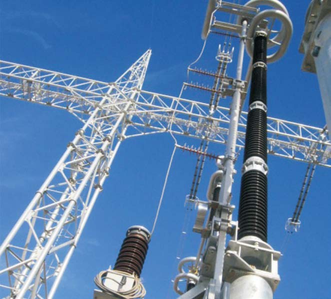
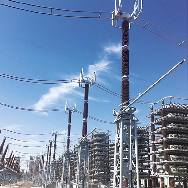
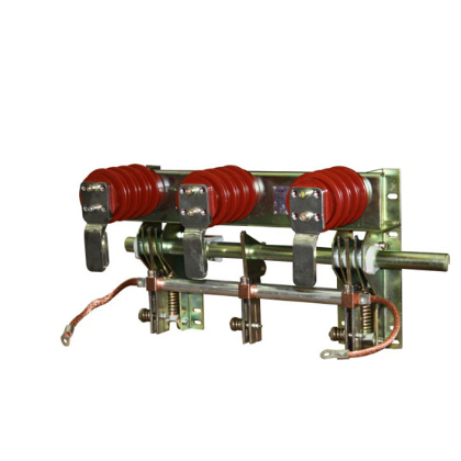
The JW6/8 series high-voltage grounding switches feature a three-single-pole configuration integrated with an operating mechanism. Each single pole comprises a base, a pillar insulator, and a conductive rod: the rod is mounted on the base, while the static contact is positioned at the top of the insulator.
Driven by the operating mechanism, the conductive rod rotates upward from the horizontal position via transmission components, latching or inserting into the static contact to achieve switch closure; the opening process reverses this motion.
Main Features:
Streamlined Design & Versatility:The product’s simple, rational structure enables effortless assembly, transportation, installation, and debugging, adapting to diverse field requirements.
High-Performance Conductive Components:Constructed from high-strength alloy profiles, the conductive rods offer excellent electrical conductivity, robust mechanical strength, and lightweight design. Their superior anti-corrosion properties ensure prolonged service life in harsh environments.
Technical parameter:

How is the indoor high-voltage AC grounding switch electrically tested?
Insulation Resistance Test: Use an insulation resistance tester to measure the insulation resistance of the grounding switch. The insulation resistance value should meet the product standards and relevant electrical codes. Generally, for indoor high-voltage AC grounding switches, the insulation resistance should be in the range of several gigohms or more to ensure good insulation performance during operation and prevent leakage accidents.
Loop Resistance Test: Measure the loop resistance of the grounding switch using a dedicated loop resistance tester to check if the contact points are in good condition. The loop resistance value should fall within the specified range. If the loop resistance is too high, it may cause significant heating when current flows through the grounding switch, affecting its normal operation.
Grounding Performance Check: Ensure that the grounding connection is reliable and that the grounding resistance meets the requirements. If the grounding resistance is too high, it may prevent the current from being effectively discharged to the ground during a fault, thus failing to provide adequate protection for maintenance personnel and equipment.

Related Products


Related Knowledges
-
 How does the oil in oil-immersed power transformers clean itself?The self-cleaning mechanism of transformer oil is typically achieved through the following methods: Oil Purifier FiltrationOil purifiers are common purification devices in transformers, filled with adsorbents such as silica gel or activated alumina. During transformer operation, convection caused by oil temperature changes drives the oil to flow downward through the purifier. Moisture, acidic substances, and oxidation byproducts in the oil are absorbed by the adsorbent, thereby maintaining oil c12/06/2025
 -
 Avoid H59 Transformer Failure with Proper Inspection & CareMeasures to Prevent H59 Oil Immersed Power Distribution Transformer from Burning OutIn power systems, H59 Oil Immersed Power Distribution Transformer play an extremely critical role. Once burned out, they can cause widespread power outages, directly or indirectly affecting the production and daily lives of a large number of electricity users. Based on the analysis of multiple transformer burnout incidents, the author believes that a considerable number of such failures could have been avoided or12/06/2025
 -
 Top Causes of H59 Distribution Transformer Failure1. OverloadFirst, with the improvement of people's living standards, electricity consumption has generally increased rapidly. The original H59 distribution transformers have small capacity—“a small horse pulling a big cart”—and cannot meet user demands, causing the transformers to operate under overload conditions. Second, seasonal variations and extreme weather conditions lead to peak electricity demand, further causing H59 distribution transformers to run overloaded.Due to long-term overload o12/06/2025
 -
 How to Select H61 Distribution Transformers?H61 Distribution Transformer Selection includes the selection of transformer capacity, model type, and installation location.1.Selection of H61 Distribution Transformer CapacityThe capacity of H61 distribution transformers should be selected based on the current conditions and development trends of the area. If the capacity is too large, it results in the “large horse pulling a small cart” phenomenon—low transformer utilization and increased no-load losses. If the capacity is too small, the tran12/06/2025
 -
 Can the secondary neutral of a control transformer be grounded?Grounding the secondary neutral of a control transformer is a complex topic involving multiple aspects such as electrical safety, system design, and maintenance.Reasons for Grounding the Secondary Neutral of a Control Transformer Safety considerations: Grounding provides a safe path for current to flow to earth in the event of a fault—such as insulation failure or overload—instead of passing through the human body or other conductive paths, thereby reducing the risk of electric shock. System sta12/05/2025
 -
 Wiring Methods and Parameters of Grounding TransformersGrounding Transformer Winding ConfigurationsGrounding transformers are classified by winding connection into two types: ZNyn (zigzag) or YNd. Their neutral points can be connected to an arc suppression coil or a grounding resistor. Currently, the zigzag (Z-type) grounding transformer connected via an arc suppression coil or a low-value resistor is more commonly used.1. Z-Type Grounding TransformerZ-type grounding transformers come in both oil-immersed and dry-type insulation versions. Among them12/05/2025
Related Solutions
-
 Intelligent Operation Solution for 12kV Vacuum Circuit Breakers: Integrating Real-time Monitoring & Lifetime OptimizationⅠ. Equipment Operation & MaintenanceIntelligent Monitoring System IntegrationMulti-parameter Real-time Monitoring: Embedded sensors (temperature, displacement, Hall effect current sensors) track contact temperature rise, mechanical characteristics (opening/closing speed, overtravel), coil current, and partial discharge signals. Data undergoes preprocessing via edge computing prior to cloud upload.Lifetime Prediction Model: Dynamically evaluates remaining lifespan using electrical wear data06/10/2025
 -
 SF6 Circuit Breaker Solutions for Outdoor Installation (Anti-Pollution & Seismic Resistance)I.Core Challenges in Outdoor InstallationIn high-voltage transmission and distribution systems, SF6 circuit breakers are exposed to complex outdoor environments for extended periods, facing the following critical issues:Pollution & Insulation DegradationDust, salt fog, and industrial pollutants in outdoor environments easily adhere to equipment surfaces. In coastal or industrial areas, pollution levels may reach Class IV, resulting in insufficient creepage distance and triggering flasho05/12/2025
 -
 12kV Indoor Vacuum Circuit Breaker Southeast Asia Solution: Anti-Corrosion Compact Design12kV Indoor Vacuum Circuit Breaker Southeast Asia Solution: Anti-Corrosion Compact DesignⅠ. Executive SummarySoutheast Asia faces rapidly growing electricity demand alongside environmental challenges including high temperatures, humidity, salt spray corrosion, and grid instability. This solution recommends Solid Insulated Pole-Mounted Vacuum Circuit Breakers (VCB) featuring high reliability, compact design, and smart monitoring. Tailored for tropical climates and industrial scenarios, it06/10/2025


