I. Príomhchúis Dianaimh: Tionchar Deindimeach (Comhdhéanamh le GB/T 1094.5 / IEC 60076-5)
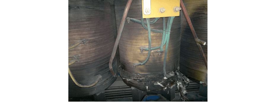
Is é an chúis dhaingineach do chur isteach ar deireadh na scuad airde voltáil go forleathan an tionchar deindimeach láidir a spreagann an cairr amháin ghruaim. Nuair a tharlaíonn tionscadal gréasáin aon phhaisnéise sa chóras (mar shampla, réabhlóid gealtán, briseadh cosaint, srl.), is é an transfoirméir greasáin an bealach don gcuir amháin ghruaim, agus tuigeann sé cúrsaí amháin ghruaim le mheastacht mhór agus ráta ard rása. De réir dlí Fhuinneamh Ampère, cuireann córais conaidte scuadeanna faoi fhorbairt radach (compordú isteach) agus ascaill (tensile/compressive) deindimeacha i réim bheatha magnatacha láidir. Má théann an tionchar deindimeach thar teorainn neart meicniúil struchtúr na scuad (conaidte, spásaithe, pláití compordú, córais cáinte), déanfaidh sé dúshlán neamhathraitheach, athrú suíomh, nó míchruinniú ar na scuad, ag cur síos ina dhiaidh sin mar choipcheann scuad - modh tíocha coitianta uirlisí tranaformála le linn tionscadail amháin ghruaim.
II. Tionscadail Cothrom Coiriúnach: Réabhlóid Bhreisvoltáil agus Ionchúisigh le Tionscadail Fágála (Comhdhéanamh le Srianraí Cosanta Breisvoltaí mar DL/T 620 / IEC 60099)
Réabhlóid Bhreisvoltáil Córas (Ferroresonance / Linear Resonance)
Níl a oireadh iompair paramaithe córas (capacitance líne, PT inductance, inductance coil greasa, srl.) féadfaí a spreagadh ferroresonance nó linear resonance, ag cruthú breisvoltáil leanúnach. Léiríonn an breisvoltáil seo go leanúnach ar shuíomhí dheacair cosaint (cosaint seanda, arresters, bushings, srl.), ag cur síos ar ghréasán greasa neamhchinnteach nó briseadh atá á dtarchur, ag cur an transfoirméir greasáin faoi thréimhseach impact currents uafásach. Ní hamháin go cruthaíonn sé seo go díreach tionchar deindimeacha, ach gníomhaíonn sé freisin chun aisteoirí teo agus leictreach cosaint scuad (inter-turn, inter-layer, agus príomh-cosaint) a chur chun cinn, ag laghdú go mór ar a neart dielectric agus neart meicniúil, ag déanamh é níos mó ina chodarsnacht le titim le linn impacats nua-aimseartha nó feidhmíocht gnách.
Ionchúisigh le Tionscadail Leanúnacha tar éis Géarfhada
Tar éis do ghearrfhad a spreagadh tionscadal greasáin leanúnach sa líne, má tá an pointe tionscadail gan a aistriú (mar shampla, an circuit breaker nach bhfuil trioblóid trí nó a léiriú ar an tionscadal), déanann foirne cothabhála ionchúisigh míchruinn (ionchúisigh le tionscadail), ag cur an transfoirméir greasáin faoi thuaisceol fault current (go mór níos mó ná an teorainn dearaithe). Tuigeann an overcurrent súgach éifeacht Joule heating I²Rt, ag cur teocht na scuad suas go tapa thar an teorainn cosaint (mar shampla, 105°C do Chlas A), ag cur síos ar aisteoireacht teo, carbonization, agus caill cosaint, ag cur síos ina dhiaidh sin mar short-circuit scuad agus burnout (titim teo). Cruthaíonn an staid seo damáiste uafásach ar an tionscal.
III. Scéim Óptaim: Meastú Neart Uirlisí agus Comhlíonadh Stratuithe Cosanta (Integrating Equipment Selection, Relay Protection, and Condition Monitoring Standards)
Fardachú Neart Short-Circuit An Chuid (Comhdhéanamh le GB/T 1094.5 / IEC 60076-5)
Rialacha Roghnaithe: Prioritize high short-circuit resistance models verified by strict short-circuit withstand tests (e.g., IEC 60076-5) for subsequent purchases, focusing on winding structure design (reinforced press plates, axial clamping systems, radial support structures, transposition conductor processes), material strength, and manufacturing processes.
Series Current-Limiting Reactor Roghnaithe: Install a current-limiting reactor in the neutral circuit of the grounding transformer to effectively suppress the amplitude and rise rate of fault currents, reducing electrodynamic impacts on windings. The impact on the system grounding mode and relay protection must be verified simultaneously.
Cosaint Relay Configurations agus Setting (Comhdhéanamh le Srianraí Cosanta Relay DL/T 584 / DL/T 559)
Principles Setting: The overcurrent protection settings (zero-sequence overcurrent, inverse-time overcurrent) of the grounding transformer must be strictly lower than the equipment's thermal and dynamic stability limits (calculated per GB/T 1094.5).
Gradation Coordination: The protection time delay of the grounding transformer (e.g., 100A/10s) must reliably coordinate with the upstream line protection (outgoing circuit breaker). Ensure that the line protection (zero-sequence Stage I: 0.2s, Stage II: 0.7s) can quickly clear grounding faults on the line, preventing the grounding transformer from enduring unnecessary stress. The grounding transformer protection, as a close backup, should have an operation time delay greater than the longest time delay of the line protection (including the gradation Δt).
Optimization of Grounding Transformer Body Protection Settings:
Strengthening Fault Fast-Clearing Capability (Complying with DL/T 584 / DL/T 559)
Directional Zero-Sequence Protection Configuration: Deploy and reliably activate directional zero-sequence current protection (Stage I/II) in line protection. The direction element accurately distinguishes between faulted and non-faulted lines, ensuring that the faulted line circuit breaker trips reliably within ≤0.2s during single-phase grounding faults, completely isolating the fault source—this is the core protection measure to prevent grounding transformer damage.
Deploying Intelligent On-Line Monitoring and Early Warning Systems (Complying with Condition Monitoring Standard DL/T 1709.1)
Real-Time Winding Hot Spot Temperature Monitoring: Install optical fiber or platinum resistance temperature sensors at key positions of the high-voltage winding ends to achieve real-time monitoring with ±1~2℃ accuracy. Set multi-level alarms (warning/alert) and tripping thresholds (calculated based on insulation class thermal models), automatically triggering protection actions when limits are exceeded to prevent thermal collapse.
Neutral Point Electrical Parameter Monitoring and Asymmetry Alarm: Continuously monitor neutral point current and system displacement voltage (zero-sequence voltage), and configure asymmetry over-limit alarm functions. When persistent/frequent abnormal neutral point electrical parameters are detected (indicating intermittent grounding, resonance, or insulation degradation), issue immediate warnings for early fault intervention.
Conclusions Óptaim agus Moltaí Impleachta
Achoimre Conclusions
Fardachú Uirlisí: Select high short-circuit resistance equipment or install current-limiting reactors to enhance electrodynamic tolerance.
Protection Coordination: Precisely set protection values (≤equipment tolerance limits) and ensure gradation coordination with directional zero-sequence protection (Stage I ≤0.2s).
Condition Early Warning: Deploy high-precision temperature monitoring (±1~2℃) and neutral point electrical parameter alarm systems for early fault protection.
The direct cause of the accident is that the electrodynamic force generated by the single-phase grounding fault current exceeds the mechanical strength limit of the windings.
Deep-level triggers include: ① Intermittent impacts caused by system resonant overvoltage accelerating insulation aging; ② Thermal collapse due to energization with permanent faults after lightning strikes.
Systematic optimization should focus on three aspects:
Moltaí Impleachta
Immediate implementation of protection setting adjustments, directional protection activation, and monitoring system installation.
Plan equipment body upgrades in conjunction with service life cycles and technical transformation schedules.
Incorporate this scheme into operation regulations and anti-accident measures, strictly prohibiting energization with grounding faults, and thoroughly investigating fault points before restoring power after lightning strikes.


