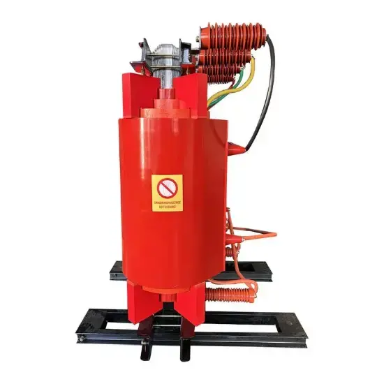
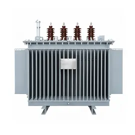
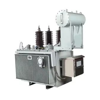
A zig-zag grounding transformer, also called a zig-zag earthing transformer or neutral earthing transformer, is a special-purpose transformer used in medium-voltage power systems. Its main function is not to transform voltage or transfer load power, but to create a stable neutral point for systems that do not have one, or where the neutral point is not readily accessible.
This neutral point can then be connected to an arc suppression coil, neutral grounding resistor, or small reactor to support system earthing, fault current control, and protection coordination.
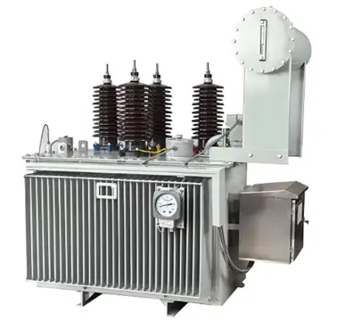
IEC Oil-Immersed Zigzag Earthing Transformer Manufacturer
Why Is a Grounding Transformer Needed?
In 6 kV, 10 kV, 35 kV and similar medium-voltage distribution networks, the low-voltage side of the main transformer is often connected in delta, or the star point is not brought out. As a result, the system has no neutral point available for earthing during normal operation.
However, a neutral point is still required for several reasons:
-
Limiting arc-ground overvoltages
During a single-phase earth fault, large capacitive currents may cause intermittent arcing at the fault point. This can generate high overvoltages that threaten cables, switchgear, instrument transformers and other equipment.
-
Providing a zero-sequence current path
Earth faults produce zero-sequence current. Without a neutral point, there is no stable return path, and zero-sequence protection may not operate sensitively.
-
Supporting arc suppression coils or low-resistance earthing
When connected through an arc suppression coil, the system can compensate capacitive earth-fault current. When connected through a neutral grounding resistor, fault current can be limited while ensuring reliable operation of zero-sequence protection.
-
Improving supply reliability
Many medium-voltage systems allow short-time operation during a single-phase earth fault. A properly designed neutral earthing arrangement helps maintain stable system voltages until the fault is cleared.
Therefore, when the power system does not provide a neutral point, a grounding transformer is used to create one.
Structure of a Zig-Zag Grounding Transformer
A zig-zag grounding transformer usually has a similar core-type construction to a conventional three-phase transformer, but its winding connection is different.
Each phase winding is divided into two equal halves with opposite directions. These halves are wound on different core limbs and then connected in series in a zig-zag arrangement. The common point of the three phases is brought out as the neutral point N.
For example, phase A is not wound only on the A-phase core limb. Part of its winding is linked with another phase, such as phase B or phase C. After cross-connection, the windings form a zig-zag pattern.
Common vector groups include:
- ZN: HV side with zig-zag connection and neutral brought out;
- ZNyn1 / ZNyn11: HV side with zig-zag connection and LV side with star-connected secondary winding, which can also serve as a station service transformer.
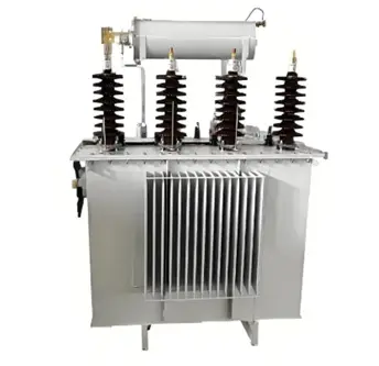
China Oil Immersed Grounding Transformer Manufacturer
How Does a Zig-Zag Grounding Transformer Work?
The key characteristic of a zig-zag grounding transformer is that it presents high impedance to positive- and negative-sequence currents, but low impedance to zero-sequence currents.
1. Under normal conditions: nearly no-load operation
When the three-phase system voltages are balanced, only a small excitation current flows through the grounding transformer. The zig-zag winding presents high excitation impedance to positive- and negative-sequence voltages, so normal losses are very low and the transformer absorbs almost no active power.
2. During a single-phase earth fault: low-impedance path for fault current
When a single-phase earth fault occurs, zero-sequence voltage and zero-sequence current appear. Zero-sequence current flows from the neutral point into the three-phase windings. The zero-sequence currents in all three phases are equal in magnitude and identical in phase.
Because the two half-windings on the same core limb have opposite directions and opposite polarity, their zero-sequence magnetomotive forces cancel each other. The resultant zero-sequence flux is therefore very small.
As a result, the zero-sequence impedance is mainly determined by leakage reactance and remains relatively low. The exact value depends on system voltage level, winding design, manufacturing details and project requirements.
This provides a low-impedance path for zero-sequence current, allowing fault current to flow smoothly through the neutral point into the earthing device.
Why Is Zig-Zag Connection Preferred for Grounding Transformers?
Grounding transformers are not limited to zig-zag connection, but the zig-zag arrangement offers clear advantages in medium-voltage earthing applications.
1. Low zero-sequence impedance
The zig-zag winding allows zero-sequence MMFs to cancel on each core limb, resulting in low zero-sequence impedance and smooth flow of earth-fault current.
2. Low normal operating losses
Under balanced conditions, the transformer draws only a small excitation current and operates close to no-load, keeping standby losses low.
3. Good compatibility with arc suppression coils and neutral grounding resistors
For arc suppression coil earthing, the zig-zag transformer allows compensation current to flow freely, enabling high utilization of the coil capacity.
For low-resistance earthing, it provides sufficient zero-sequence current for sensitive and reliable protection operation.
By comparison, when a conventional YNyn transformer is used to connect an arc suppression coil, the coil capacity is usually limited to a small proportion of the transformer rating. With YNd transformers, utilization is also constrained by secondary loading and additional losses.
4. Can also serve as a station service transformer
Many zig-zag grounding transformers are provided with a low-voltage secondary winding, forming a ZNyn connection. This allows the unit to provide both a neutral earthing point and 380/220 V auxiliary power for the substation, reducing investment and space requirements.
5. Some suppression of third-harmonic components
The zig-zag connection can help suppress third-harmonic and other zero-sequence harmonic components, improving voltage waveform quality. However, this is usually a secondary benefit rather than the main reason for selection.
Zig-Zag Grounding Transformer vs. Conventional Transformer
| Comparison item |
Zig-zag grounding transformer |
Conventional transformer |
| Main purpose |
Provide artificial neutral point and support earthing protection |
Transform voltage and transfer power |
| Winding structure |
Each phase split into two parts with zig-zag connection |
Standard Y, Δ or YN connection |
| Neutral point |
Brought out specifically for earthing |
May be absent or not used for earthing |
| Zero-sequence impedance |
Low, suitable for zero-sequence current |
Higher, limits zero-sequence current |
| Operating condition |
Nearly no-load in normal operation; carries short-time fault current |
Continuously loaded during normal operation |
| Typical application |
MV earthing, arc suppression coils, neutral grounding resistors |
Main transformers and distribution transformers |
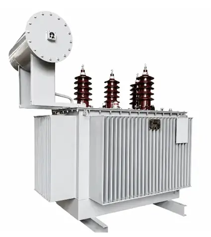
Z-type Oil-Immersed Earthing Transformer OEM China
Typical Applications
-
10 kV and 35 kV distribution networks
Used when the main transformer LV side is delta-connected or the system neutral is not available.
-
Arc suppression coil earthing systems
Used to compensate capacitive earth-fault current, extinguish arcing faults and limit transient overvoltages.
-
Low-resistance earthing systems
Used to limit earth-fault current while ensuring reliable operation of zero-sequence protection.
-
Renewable energy plants, industrial networks and data centres
Used in inverter-interfaced systems, delta-connected networks or isolated power systems to provide a stable earthing point and improve unbalanced voltage and protection performance.
Selection and Operation Considerations
- Match the system voltage level, such as 6 kV, 10 kV or 35 kV, to the rated system voltage.
- Design zero-sequence impedance carefully. Too low a value may increase fault current excessively; too high a value may reduce protection sensitivity. It must be coordinated with the neutral grounding resistor or arc suppression coil.
- Select capacity appropriately. When used only for earthing, the primary rating should match the arc suppression coil or neutral grounding resistor. When only an arc suppression coil is connected, the primary capacity is commonly selected at 1.05 to 1.15 times the coil rating as an engineering practice. If a secondary load is also supplied, the station service load must be added.
- Check short-time thermal capability. The transformer operates nearly no-load under normal conditions but must withstand short-time earth-fault current.
- Confirm the vector group, such as ZN, ZNyn1 or ZNyn11, according to protection, measurement and auxiliary power requirements.
- Verify whether a grounding transformer is actually required. If the main transformer already has an accessible neutral point, for example in some 35 kV or 110 kV YN-connected systems, a separate grounding transformer may not be necessary.
Relationship with IEC Standards
Within the IEC framework, zig-zag grounding transformers are generally designed and tested according to the general requirements for power transformers in the IEC 60076 series. IEC 60076-25 primarily covers neutral earthing resistors and explicitly recognizes their use together with zig-zag transformers, open-delta transformers and arc suppression coils.
In practice, zig-zag grounding transformers are specified and verified according to the required zero-sequence impedance, short-time fault current, rated voltage, cooling method, insulation level and test programme. Compliance with any particular project should always be confirmed against the contract technical specification, the applicable edition of the standard and third-party test reports.
Summary
A zig-zag grounding transformer is a special transformer that creates an artificial neutral point through a zig-zag winding arrangement. It is widely used because it presents high impedance under normal balanced conditions, resulting in low losses, while providing low impedance to zero-sequence current during single-phase earth faults. This makes it well suited for arc suppression coils, neutral grounding resistors and zero-sequence protection schemes.
Compared with conventional transformers, zig-zag earthing transformers offer clear advantages in medium-voltage distribution networks, especially for earth-fault current control, system earthing and reliability improvement.

 Login