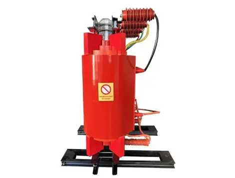
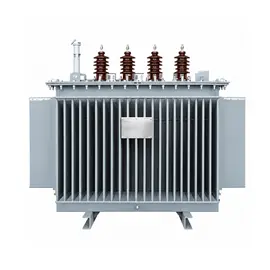
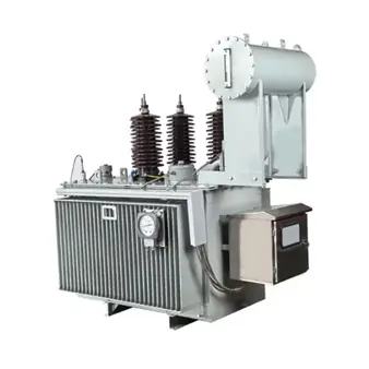
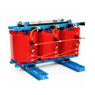
A dry-type grounding transformer provides an artificial neutral point for three-phase systems that do not have a naturally accessible neutral. Once the neutral point is established, it can be connected to an arc suppression coil, earthing resistor, neutral point reactor, or other auxiliary devices, forming a complete neutral grounding arrangement together with isolating switches, current transformers, surge arresters, or spark gaps.
What Equipment Can Be Connected to the Neutral Point?
| Equipment |
Main Function |
IEC-Related Note |
| Arc suppression coil / Petersen coil |
Compensates single-phase earth fault capacitive current and helps extinguish the arc |
Rated values, short-time capability and insulation levels can be referenced to IEC 60076-6 |
| Earthing resistor |
Limits earth fault current, suppresses overvoltage and provides detectable zero-sequence current |
Resistance is selected based on phase-to-neutral voltage and target fault current; short-time thermal withstand must be verified |
| Neutral point reactor |
Limits zero-sequence current or suppresses resonance in series with the arc suppression coil |
Can be treated as a neutral point earthing reactor under IEC 60076-6 |
| Surge arrester / spark gap |
Limits neutral point overvoltage and protects the grounding transformer |
Insulation coordination can be referenced to IEC 60071-1 and IEC 60071-2 |
| Current transformer |
Measures zero-sequence current for protection, earth fault line selection and monitoring |
Installed in the neutral point circuit |
| Isolating switch |
Provides a visible isolation point for maintenance and switching |
Should be provided in the neutral point circuit |
| Secondary load |
Supplies auxiliary power when the grounding transformer also serves as a station service transformer |
Secondary capacity must be calculated separately |
Dry-type grounding transformers commonly use a zigzag connection, such as ZNyn11 or ZNvn11. Under normal operation, they present high impedance to positive- and negative-sequence currents and carry only a small magnetizing current. During a single-phase earth fault, they present low impedance to zero-sequence current, allowing it to flow through the neutral point to the arc suppression coil or earthing resistor.
When Is an Arc Suppression Coil Suitable?
Arc suppression coils are suitable for non-effectively earthed systems, also known as resonant earthed systems or small earth fault current systems.
Typical application conditions include:
- Medium-voltage systems such as 3 kV, 6 kV, 10 kV, 20 kV, 35 kV and 66 kV.
- Systems where the single-phase earth fault capacitive current exceeds the permissible limit for an isolated neutral, but continued short-time operation during an earth fault is required.
- Networks with high supply continuity requirements, such as rural distribution networks, mines, oilfields, chemical plants, metallurgical plants, hospitals and continuous-process industrial facilities.
- Overhead line networks or mixed overhead/cable networks with frequent transient earth faults.
- Operation under overcompensation to avoid series resonance caused by near-full compensation.
Resonant earthing can limit transient overvoltages during single-phase earth faults. However, resonance must still be avoided, and higher overvoltages may occur if the compensation equipment is abnormal or improperly adjusted.
Selection guidance:
- When the capacitive earth fault current exceeds the limit permitted for an isolated neutral system and short-time faulted operation is required, an arc suppression coil may be considered. The exact limit should be determined according to applicable national standards, local utility requirements and equipment specifications.
- When capacitive current is high, especially in all-cable networks, low-resistance earthing or a combined earthing scheme may be preferred.
- When the capacitive current is close to the selection boundary, a combined scheme can be adopted: the arc suppression coil operates under normal conditions, and a parallel resistor is switched in after a time delay to clear permanent earth faults.
When Is an Earthing Resistor Suitable?
Earthing resistors are divided into low-resistance earthing and high-resistance earthing.
Low-Resistance Earthing
Typical applications include 6 kV–35 kV cable networks, urban distribution systems, industrial power systems and power plant auxiliary systems.
Key characteristics:
- Earth fault current is relatively high, typically limited to several hundred amperes.
- Zero-sequence protection can detect the fault reliably.
- Faulted feeders can be disconnected quickly.
- Transient overvoltages are effectively limited.
- Supply continuity is lower than in resonant earthed systems because the faulted circuit is tripped.
Selection considerations:
- Suitable for all-cable networks and urban underground distribution systems.
- Preferred when fast protection, accurate fault location and selective tripping are required.
- The grounding transformer, earthing resistor and switchgear must be verified for short-time thermal withstand based on the expected earth fault current and fault clearing time.
The resistance value can be preliminarily estimated as:
R = V_ln / I_f
where V_ln is the system phase-to-neutral voltage and I_f is the target single-phase earth fault current. This expression is a simplified selection basis. The final value must also consider system voltage variation, earthing scheme, protection settings, capacitive current and equipment thermal limits.
High-Resistance Earthing
High-resistance earthing is used where earth fault current must be limited, resonance overvoltages should be suppressed, and short-time continued operation is acceptable.
Key characteristics:
- Earth fault current is usually limited to a few amperes up to several tens of amperes.
- The system may continue operating temporarily, but the fault should be located and cleared promptly.
- Commonly applied in generator terminals, auxiliary power systems and small distribution systems.
Arc Suppression Coil vs. Low-Resistance Earthing
| Comparison |
Arc Suppression Coil Earthing |
Low-Resistance Earthing |
| Earth fault current |
Low residual current |
Typically several hundred amperes |
| Fault handling |
Arc extinction; short-time continued operation possible |
Fast tripping of the faulted feeder |
| Supply continuity |
Higher |
Lower |
| Overvoltage control |
Limits transient overvoltages; resonance must be avoided |
Effective overvoltage limitation |
| Protection |
Depends on earth fault line selection; tripping is not always immediate |
Zero-sequence protection trips the faulted circuit |
| Typical network |
Overhead or mixed networks with high reliability requirements |
Cable networks, urban and industrial distribution systems |
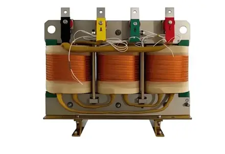
dry-type grounding transformer
Neutral Point Protection and Operating Requirements
In addition to the main neutral point equipment, the following protection and operating measures should be considered:
- An isolating switch should be installed to provide a visible isolation point.
- A current transformer should be provided for zero-sequence current measurement, protection and earth fault line selection.
- Surge arresters or spark gaps should be considered to limit neutral point overvoltage.
- The grounding transformer should be equipped with zero-sequence overcurrent protection, coordinated with the system earthing scheme.
- Normally, only one grounding transformer neutral point should be connected on the same busbar section, with position interlocking applied.
- Resonant earthed systems should be equipped with single-phase earth fault line selection.
- Low-resistance earthed systems must ensure reliable zero-sequence protection operation and verify the thermal withstand of the earthing resistor.
- Insulation levels should be checked through insulation coordination in accordance with IEC 60071-1 and IEC 60071-2.
Selection Recommendations
- When the low-voltage side of the main transformer is delta-connected and has no accessible neutral point, a grounding transformer should be provided.
- When capacitive earth fault current is relatively low and short-time continued operation is acceptable, an arc suppression coil is often preferred.
- When the network has many cable circuits, high capacitive current, and fast fault clearing is required, low-resistance earthing is often more suitable.
- When the capacitive current is close to the selection boundary, a combined scheme may be adopted: the arc suppression coil operates during normal conditions, and a parallel resistor is switched in for permanent earth faults.
- The grounding transformer rating must match the neutral point equipment. For arc suppression coil earthing, the transformer should satisfy the coil rating, short-time duty and thermal requirements. For resistor earthing, it should be verified against the short-time earth fault current and fault duration. If the grounding transformer also supplies auxiliary power, the secondary load capacity must be calculated separately.
- Typical short-time ratings include 10 s, 30 s and 60 s, but the final value should be determined according to protection clearing time, system operating conditions and manufacturer specifications.
- The neutral point circuit should be designed as a complete arrangement, including isolating switches, current transformers, surge arresters or spark gaps, and necessary protection devices.
In summary, the neutral point of a dry-type grounding transformer is mainly used to connect an arc suppression coil, earthing resistor and associated protection and measurement equipment. Arc suppression coil earthing is more suitable for networks requiring high supply continuity and controlled earth fault currents.
Low-resistance earthing is more suitable for cable-rich urban and industrial networks where fast fault clearance is required. Final parameters and equipment selection should comply with applicable IEC standards, local utility regulations and the technical conditions of the equipment manufacturer.

 Login