Application of SVR Feeder Automatic Voltage Regulators in Rural Distribution Networks

1. Introduction
In recent years, with the steady and rapid development of the national economy, electricity demand has grown significantly. In rural power grids, the continuous increase in load, combined with irrational distribution of local power sources and limited voltage regulation capabilities in the main grid, has resulted in a considerable number of 10 kV long feeders—particularly in remote mountainous areas or regions with weak grid structures—whose supply radius exceeds national standards. Consequently, the voltage quality at the end of these 10 kV lines is difficult to guarantee, the power factor fails to meet requirements, and line losses remain high.
Due to constraints such as limited grid construction funding and investment return considerations, it is impractical to solve all low-voltage-quality issues on 10 kV distribution feeders solely by deploying numerous high-voltage distribution substations or excessively extending the grid. The 10 kV feeder automatic voltage regulator introduced below offers a technically viable solution for addressing poor voltage quality on long-distance distribution lines with extended supply radii.
2. Working Principle of the Voltage Regulator
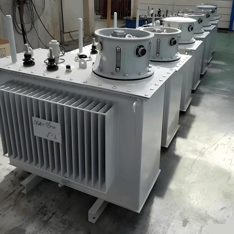
The SVR (Step Voltage Regulator) automatic voltage regulator consists of a main circuit and a voltage regulation controller. The main circuit comprises a three-phase autotransformer and a three-phase on-load tap changer (OLTC), as illustrated in Figure 1.

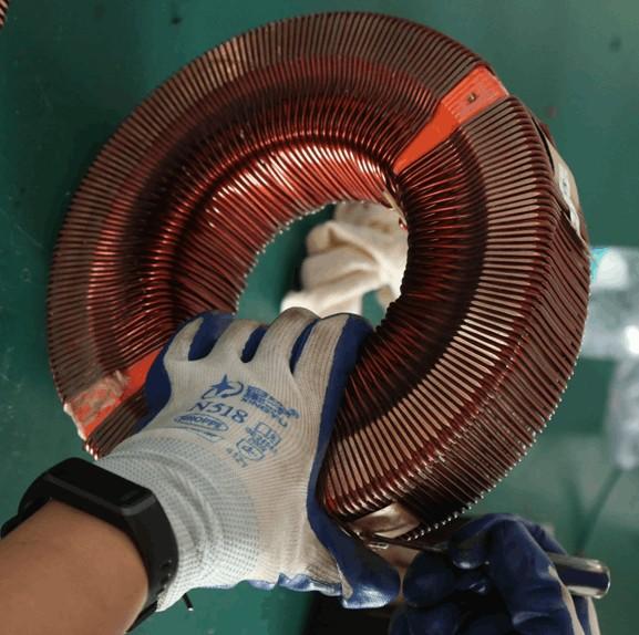
The regulator winding system includes a shunt winding, a series winding, and a control voltage winding:
The series winding is a multi-tap coil connected between the input and output via different contacts of the tap changer; it directly regulates the output voltage.
The shunt winding serves as the common winding of the autotransformer, generating the magnetic field necessary for energy transfer.
The control voltage winding, wound over the shunt winding, acts as a secondary of the shunt coil to supply operating power for the controller and motor, as well as provide voltage signals for output measurement.
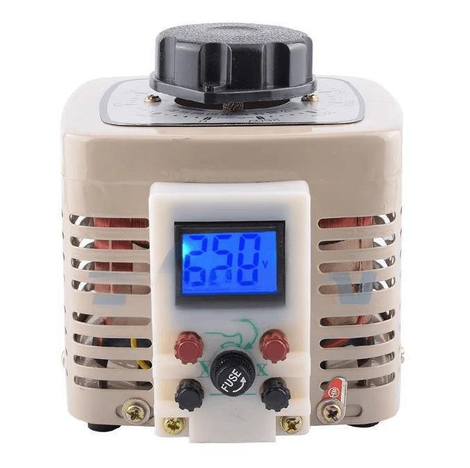
The working principle is as follows: By connecting the taps of the series winding to different positions of the on-load tap changer, the turns ratio between the input and output windings is altered through controlled switching of tap positions, thereby adjusting the output voltage. Depending on application requirements, on-load tap changers are typically configured with either 7 or 9 tap positions, allowing users to select the appropriate configuration based on actual voltage regulation needs.
The turns ratio between the primary and secondary windings of the regulator is consistent with that of a conventional transformer, i.e.:

3.Application Example
3.1 Current Line Conditions
A certain 10 kV distribution line has a main feeder length of 15.138 km, constructed with two conductor types: LGJ-70 mm² and LGJ-50 mm². The total capacity of distribution transformers along the line is 7,260 kVA. During peak load periods, the voltage on the 220 V side of distribution transformers in the middle-to-end sections of the line drops as low as 175 V.

The LGJ-70 conductor has a resistance of 0.458 Ω/km and a reactance of 0.363 Ω/km. Therefore, the total resistance and reactance from the substation to Pole #97 on the main feeder are:
R = 0.458 × 6.437 = 2.95 Ω
X = 0.363 × 6.437 = 2.34 Ω
Based on the distribution transformer capacity and load factor along the line, the voltage drop from the substation to Pole #97 on the main feeder can be calculated as

The symbols used are defined as follows:
Δu — voltage drop along the line (unit: kV)
R — line resistance (unit: Ω)
X — line reactance (unit: Ω)
r — resistance per unit length (unit: Ω/km)
x — reactance per unit length (unit: Ω/km)
P — active power on the line (unit: kW)
Q — reactive power on the line (unit: kvar)
Thus, the voltage at Pole #97 on the main feeder is only:
10.4 kV − 0.77 kV = 9.63 kV.
Similarly, the voltage at Pole #178 can be calculated as 8.42 kV, and the voltage at the line end is 8.39 kV.
3.2 Proposed Solutions
To ensure voltage quality, the primary voltage regulation methods in medium- and low-voltage distribution networks include:
Constructing a new 35 kV substation to shorten the 10 kV supply radius.
Replacing conductors with larger cross-sectional areas to reduce line loading.
Installing line-based reactive power compensation—however, this method is less effective for long lines with heavy loads.
Installing an SVR feeder automatic voltage regulator, which offers high automation, excellent voltage regulation performance, and flexible deployment.
Below, three alternative solutions for improving the end-of-line voltage quality on the 10 kV "Fakuai" feeder are compared.
3.2.1 New 35 kV Substation Construction
Expected outcome: A new substation would significantly shorten the supply radius, raise the end-of-line voltage, and improve overall power quality. While highly effective, this solution requires substantial investment.
3.2.2 Upgrading the 10 kV Main Feeder
Modifying line parameters primarily involves increasing conductor cross-section. For sparsely populated areas with small-conductor lines, resistive losses dominate total voltage drop; thus, reducing conductor resistance provides noticeable voltage improvement. With this upgrade, the end-of-line voltage can be raised from 8.39 kV to 9.5 kV.
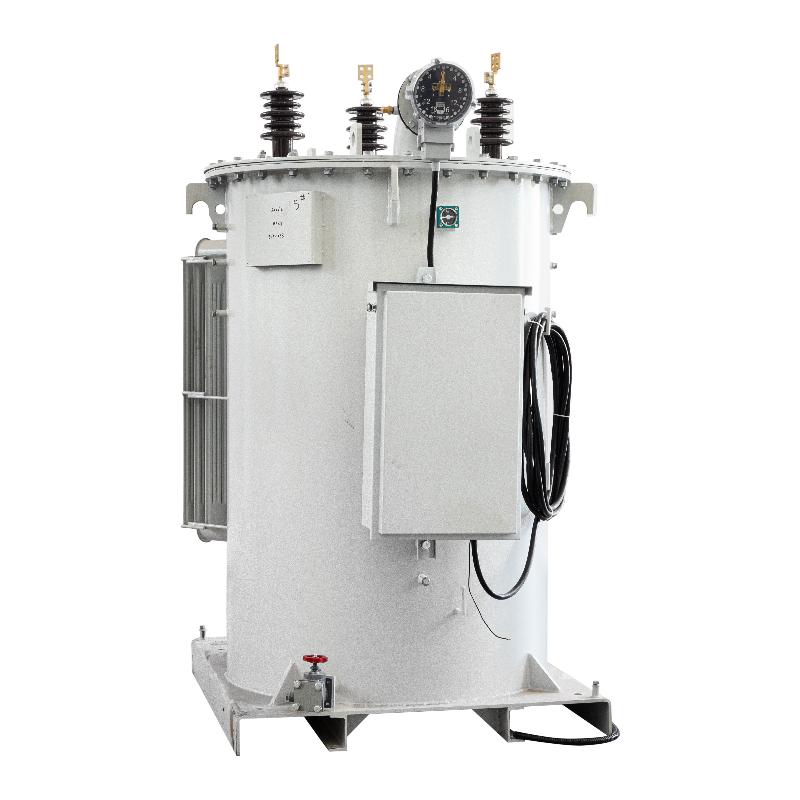
3.2.3 Installation of an SVR Feeder Automatic Voltage Regulator
One 10 kV automatic voltage regulator is installed to address low voltage issues downstream of Pole #161.
Expected outcome: The end-of-line voltage can be increased from 8.39 kV to 10.3 kV.
Comparative analysis shows that Option 3 is the most economical and practical.
The SVR feeder automatic voltage regulation system stabilizes output voltage by adjusting the turns ratio of a three-phase autotransformer, offering several key advantages:
Fully automatic, on-load voltage regulation.
Uses a star-connected three-phase autotransformer—compact size and high capacity (≤2000 kVA), suitable for pole-to-pole installation.
Typical regulation range: −10% to +20%, sufficient to meet voltage requirements.
Based on theoretical calculations, it is recommended to install one SVR-5000/10-7 (0 to +20%) automatic voltage regulator on the main feeder. After installation, the voltage at Pole #141 can be raised to:
U₁₆₁ = U × (10/8) = 10.5 kV
where:
U₁₆₁ = voltage at the regulator installation point after commissioning
10/8 = maximum turns ratio of a regulator with 0 to +20% adjustment range
Field operation has confirmed that the SVR system reliably tracks input voltage variations and maintains stable output voltage, demonstrating proven effectiveness in low-voltage mitigation.
3.2.4 Benefit Analysis
Compared to building a new substation or replacing conductors, deploying an SVR voltage regulator significantly reduces capital expenditure. It not only elevates line voltage to meet national standards—delivering strong social benefits—but also, under constant load conditions, reduces line current by raising voltage, thereby lowering line losses and achieving energy savings. This enhances the utility’s economic efficiency.
4. Conclusion
For rural distribution networks in areas with limited future load growth—particularly those lacking nearby power sources, featuring long supply radii, high line losses, heavy loading, and no planned 35 kV substations in the near term—the use of SVR feeder automatic voltage regulators offers a compelling alternative. It enables deferral or elimination of 35 kV substation construction while effectively resolving low voltage quality and reducing energy losses. Given its investment cost is less than one-tenth of a new 35 kV substation, the SVR solution delivers significant social and economic benefits and is highly recommended for widespread adoption in rural power grids.