Long-Distance Power Line Distribution: Low Voltage and Large Voltage Fluctuations
According to the "Technical Guidelines for Distribution Network Planning and Design" (Q/GDW 1738–2012), the supply radius of a 10 kV distribution line must meet the voltage quality requirements at the line’s end. In principle, the supply radius in rural areas should not exceed 15 km. However, in some rural regions, the actual supply radius may extend beyond 50 km due to low load density, small and widely dispersed electricity demand, resulting in excessively long 10 kV feeders. Such long-distance power transmission inevitably causes significantly low voltage or large voltage fluctuations at the middle and far ends of the line. The most economical solution to this issue is decentralized voltage regulation.
To ensure voltage quality, the primary voltage regulation methods and measures in medium- and low-voltage distribution networks include:
On-load tap-changing (OLTC) of substation main transformers;
Adjusting reactive power flow on the line;
Modifying line parameters;
Constructing new substations;
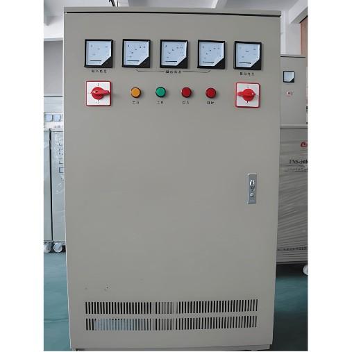
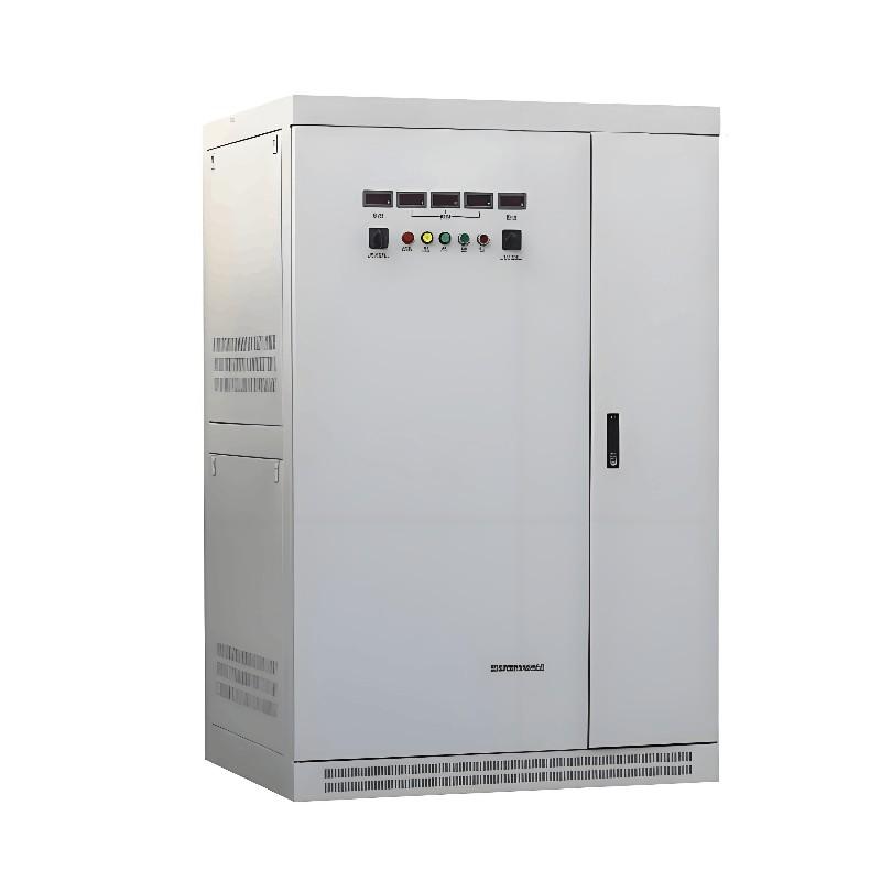
Installing SVR-series feeder automatic voltage regulators.
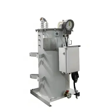
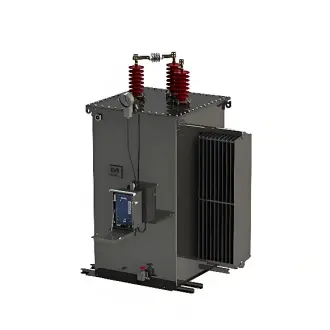
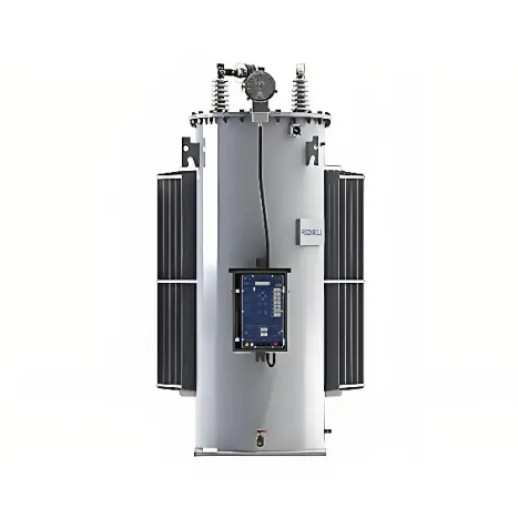
Among these, the first four approaches are often economically inefficient or impractical when applied to specific long-feed lines. Rockwell Electric Co., Ltd. has developed the SVR Feeder Automatic Voltage Regulator, which offers a technically feasible, cost-effective, and easy-to-install solution tailored for voltage regulation on such dedicated feeders.

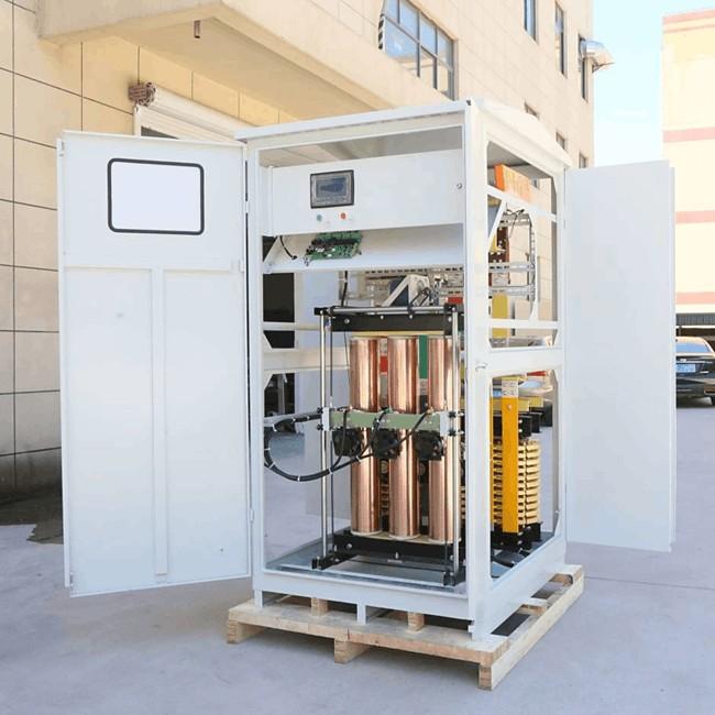
The automatic line voltage regulator consists of an autotransformer with nine taps, an on-load tap changer (OLTC), and an automatic controller capable of tracking the line-end voltage in real time based on load variations. The autotransformer comprises a main winding and a regulating winding. The voltage difference between adjacent taps on the regulating winding is 2.5%, providing a total regulation range of ±20% (i.e., 40% overall). Additionally, a secondary three-phase delta-connected winding is included primarily to suppress third-order harmonics and to supply power to the automatic controller and the OLTC mechanism.
On the source side, the main connection can be switched via the OLTC across taps 1 through 9. On the load side, the main connection is fixed according to the required regulation range:
For a regulation range of 0% to +20%, the load-side connection is fixed at tap 1 (tap 1 becomes the direct-through position);
For a range of –5% to +15%, it is fixed at tap 3 (tap 3 as direct-through);
For a symmetric range of –10% to +10%, it is fixed at tap 5 (tap 5 as direct-through).
Current transformers (CTs) are installed on phases A and C of the load side, connected in a differential configuration internally. Voltage transformers (VTs) are also installed on phases A and C of the load side. In configurations with bidirectional power flow, VTs are additionally installed on phases A and C of the source side.
The controller uses voltage and current signals from the load side as analog inputs for tap-changing decisions. Various status signals serve as the basis for identifying operational states and triggering alarms or protective actions. Based on the fundamental principle of “ensuring qualified voltage while minimizing tap operations,” and employing fuzzy control theory to blur the regulation boundaries, an enhanced control strategy has been implemented. This effectively improves voltage stability and significantly reduces the number of tap changes.
In Automatic Mode, the controller adjusts the tap position to regulate voltage:
If the load-side voltage remains below the “reference voltage” by a preset threshold for a defined duration, the controller commands the OLTC to step up. After the operation, a lockout period prevents further switching.
Once the lockout interval expires, another tap change is permitted.
Conversely, if the load-side voltage stays above the reference voltage by a set margin for a specified time, the controller initiates a step-down command, followed by a similar post-operation lockout period.
In Manual Mode, the device can be fixed at any operator-selected tap position.
In Remote Mode, it accepts commands from a remote control center and operates at the tap position specified by the remote instruction.