Seoidíonn Líne Fhuinnimh Airgidh Thar Fad: Folúntas Vóltáin Íseal agus Athruithe Móra Vóltáin
De réir "Treoracha Teicniúla um Pleanáil agus Dearadh Líonraí Díolacháin" (Q/GDW 1738–2012), ní mór do shuimir riaracháin líne díolacháin 10 kV a bheith ina chomhlíonadh ar na riachtanais cáilíochta vóltáin ag deireadh an líne. In ionsaí, ní mian go mbeadh an suimir riaracháin i réigiúnna tuaithe níos mó ná 15 km. Ach i roinnt réigiúnna tuaithe, d'fhéadfadh an suimir riaracháin fíor a bheith níos faide ná 50 km mar gheall ar ísealú luach tóimh, éileamh uisceolaíochta beag agus sástach, agus folúntas 10 kV thar fad. Seo a chuirfí orthu athruithe vóltáin íseal nó móra thar fad ag meán agus deireadh an líne. Is é an t-eolas is airgeire chun an fhadhb seo a réiteach ná rialú vóltáin neamhspleách.
Chun cáilíocht vóltáin a chinntiú, tá na modhanna agus na beartais príomha le haghaidh rialú vóltáin sa líonra díolacháin méan- agus íseal-vóltáin seo:
Athchóiriú tapa le linn oibriú (OLTC) ar mhórtróidí príomhstáisiún;
Athchóiriú sruth fuinneamh reacmhara ar an líne;
Athchóiriú paraiméad líne;
Tógáil stáisiúin nua;
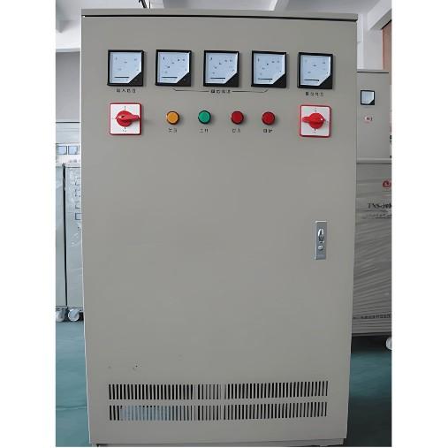
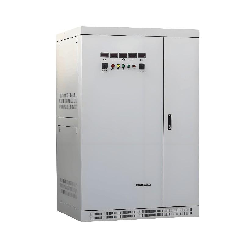
Socrú rialaitheoirí vóltáin uathoibríoch SVR-sraith.
Dianta, is minic nach bhfuil na ceithre chéad modh seo airgeire nó féideartha nuair a úsáidtear i gcónaí ar línte fhuinnimh thar fad. Tá an Rialaitheoir Vóltáin Uathoibríoch SVR feistithe ag Rockwell Electric Co., Ltd., a chuirfí orthu solútion teicniúil, airgeire, agus a bhfuil sé éasca a shocrú do rialú vóltáin ar línte fhuinnimh thar fad cosúil leis sin.

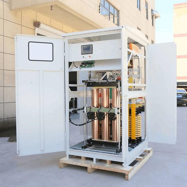
Consists of an autotransformer with nine taps, an on-load tap changer (OLTC), and an automatic controller capable of tracking the line-end voltage in real time based on load variations. The autotransformer comprises a main winding and a regulating winding. The voltage difference between adjacent taps on the regulating winding is 2.5%, providing a total regulation range of ±20% (i.e., 40% overall). Additionally, a secondary three-phase delta-connected winding is included primarily to suppress third-order harmonics and to supply power to the automatic controller and the OLTC mechanism.
On the source side, the main connection can be switched via the OLTC across taps 1 through 9. On the load side, the main connection is fixed according to the required regulation range:
For a regulation range of 0% to +20%, the load-side connection is fixed at tap 1 (tap 1 becomes the direct-through position);
For a range of –5% to +15%, it is fixed at tap 3 (tap 3 as direct-through);
For a symmetric range of –10% to +10%, it is fixed at tap 5 (tap 5 as direct-through).
Current transformers (CTs) are installed on phases A and C of the load side, connected in a differential configuration internally. Voltage transformers (VTs) are also installed on phases A and C of the load side. In configurations with bidirectional power flow, VTs are additionally installed on phases A and C of the source side.
The controller uses voltage and current signals from the load side as analog inputs for tap-changing decisions. Various status signals serve as the basis for identifying operational states and triggering alarms or protective actions. Based on the fundamental principle of “ensuring qualified voltage while minimizing tap operations,” and employing fuzzy control theory to blur the regulation boundaries, an enhanced control strategy has been implemented. This effectively improves voltage stability and significantly reduces the number of tap changes.
In Automatic Mode, the controller adjusts the tap position to regulate voltage:
If the load-side voltage remains below the “reference voltage” by a preset threshold for a defined duration, the controller commands the OLTC to step up. After the operation, a lockout period prevents further switching.
Once the lockout interval expires, another tap change is permitted.
Conversely, if the load-side voltage stays above the reference voltage by a set margin for a specified time, the controller initiates a step-down command, followed by a similar post-operation lockout period.
In Manual Mode, the device can be fixed at any operator-selected tap position.
In Remote Mode, it accepts commands from a remote control center and operates at the tap position specified by the remote instruction.