A Two-Stage DC-DC Isolated Converter for Battery-Charging Applications

This paper proposes and analyzes a two-stage dc-dc isolated converter for electric vehicle charging applications, where high efficiency over a wide range of battery voltages is required. The proposed conversion circuit comprises a first two-output isolation stage with CLLC resonant structure and a second two-input buck regulator. The transformer of the first stage is designed such that its two output voltages correspond, ideally, to the minimum and maximum expected voltage to be supplied to the battery. Then, the second stage combines the voltages provided by the previous isolation stage to regulate the output voltage of the whole converter. The first stage is always operated at resonance, with the only function of providing isolation and fixed conversion ratios with minimum losses, whereas the second stage allows output voltage regulation over a wide range of battery voltages. Overall, it is shown that the solution features high conversion efficiency over a wide range of output voltages.
1.Introduction.
Electric transportation is gaining ground in many countries due to growing concerns about global greenhouse gas emissions and fossil fuel supply and depletion. These concerns have lately propelled the exponential growth of the demand for electric vehicles (EVs) . Such a high demand combined with the strive for longer ranges and reduced charging time is pushing newer generations of EVs that implement higher battery capacities and charging rates. Consequently, new EV charging stations are needed to supply more power, more quickly than ever before.

2.Structure and Operating Principle.
As shown in Fig. the proposed two-stage converter consists of a first isolation stage based on an LLC resonant converter, and a second post-regulator stage based on a buck converter. Such a post-regulator is responsible of the output voltage regulation and it is supplied by means of a high-efficiency two-output DCX converter, with secondary voltages V1 and V2. From Fig., it is clear that the voltage stress of the post-regulator, namely, V1−V2, is lower that the output voltage Vo, which consequently allows switching devices with smaller on-resistance as well as lower switching losses.

3.Design of Llc Stage Operated As Dcx.
When the LLC resonant tank is operated at the resonance frequency, the voltage conversion ratio becomes ideally independent from the actual load. In other words, the LLC converter maintains a constant voltage conversion ratio and adjusts its current automatically, according to the load conditions, behaving as a DCX. In this operating condition, the LLC shows its maximum efficiency, with a minimum flow of reactive power and zero-voltage switching (ZVS) and zero-current switching (ZCS) conditions always satisfied . Notably, the DCX operation of the LLC does not require an external resonant inductor, because the conversion gain is fixed. An equivalent solution based on a resonant FB-LLC designed to operate over the same wide range of output voltages is expected to show higher losses than the LLC in permanent DCX conditions.

4.Conclusion
Conversion performances covering the whole power and voltage ranges have been reported experimentally, showing high efficiency over a wide range of operating conditions, recording a peak efficiency of 98.63% at 500V output voltage and 7kW transferred power. In final applications, series or parallel connections of multiple modules can be considered for scaling the voltage or current ratings of the final implementation, thanks to the isolated output. Future studies may include on-line controllers for optimal converter modulation and procedures for the optimal design of the components of the converter, like the output TBB inductors.

Source: IEEE Xplore
Statement: Respect the original, good articles worth sharing, if there is infringement please contact delete
-
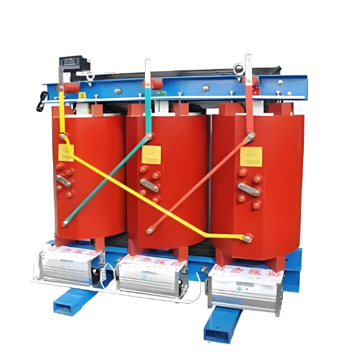
KBSG series Mining Flameproof Dry-Type Transformer

-
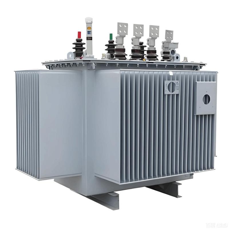
33-38kV Dry-type Distribution Transformer 800kVA/1000kVA/1250kVA/1500kVA

-
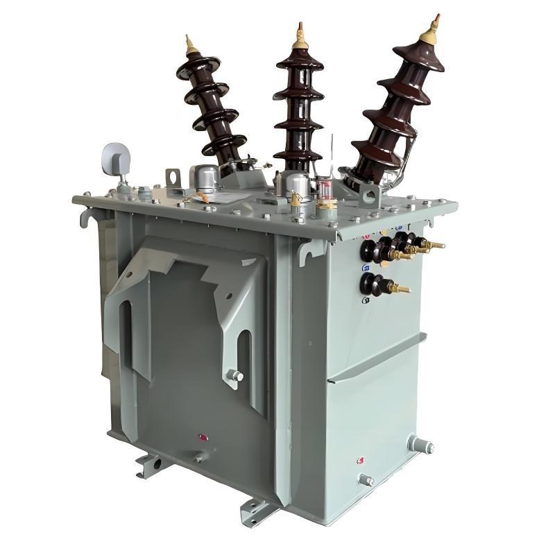
Flameproof and Intrinsically Safe Low-Voltage Protection Box for Mobile Substations in Mining Applications

-
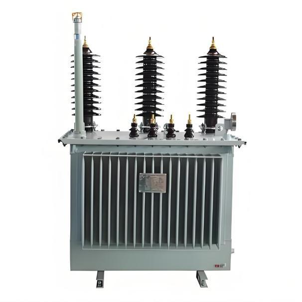
10.5kV Silicon Steel Dry Type Distribution Transformer 630kVA/800kVA/1000kVA/1250kVA /1600kVA/2000kVA