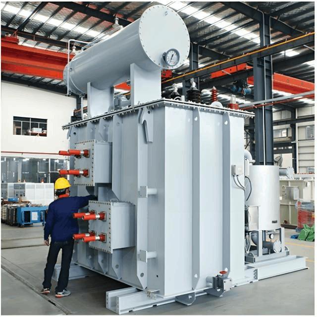
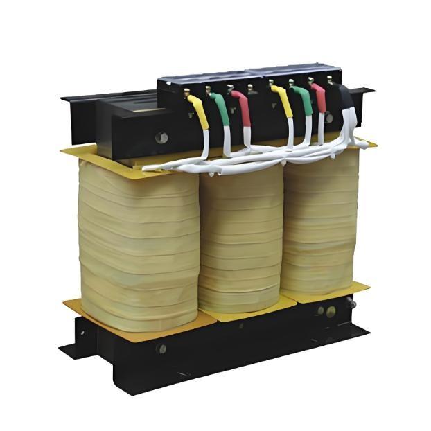
There is extensive literature on the analysis of overvoltage at transformer neutral points under lightning surge conditions. However, due to the complexity and randomness of lightning waves, an accurate theoretical description remains elusive. In engineering practice, protective measures are typically determined based on power system codes by selecting appropriate lightning protection devices, with abundant supporting documentation available.
Transmission lines or substations are susceptible to lightning strikes. Lightning surges may propagate along transmission lines into substations or directly strike substation equipment, inducing overvoltages at the transformer neutral point, which poses a threat to neutral-point insulation. Therefore, studying the characteristics of neutral-point overvoltage under lightning conditions and evaluating the voltage-limiting effectiveness of protective devices has practical significance [1]. This paper presents a simulation study using the Alternative Transients Program (ATP), the most widely used version of the Electromagnetic Transients Program (EMTP), based on the configuration of a specific 110 kV substation. By combining lightning overvoltage theory with the insulation characteristics of 110 kV transformer neutral points, the paper simulates neutral-point overvoltages under various lightning wave conditions. The simulation results are comparatively analyzed, and measures to mitigate neutral-point overvoltage are proposed.
1. Theoretical Analysis
1.1 Lightning Strike on Transmission Lines
When an overhead transmission line is struck by lightning, a traveling wave propagates along the conductor [1]. Inside substations, numerous short connecting lines (e.g., connections from transformers to busbars or surge arresters) behave similarly to transmission lines under the extremely short-duration lightning impulse. These lines exhibit rapid wave propagation, reflection, and refraction processes, often generating transient overvoltages with very high peak amplitudes that can damage equipment.
1.2 Parameter Analysis of Y-Connected Transformer Windings under Lightning Surge
Three-phase transformer windings are generally connected in Y, Yo, or Δ configurations. During operation, lightning surges may enter through one, two, or even all three phases [1]. This paper focuses on Y-connected windings, as only such configurations have an accessible neutral point. When a transformer is connected in Yo and mutual coupling between phases is neglected, whether one, two, or three phases are struck, the system can be analyzed as three independent windings with grounded terminals.
2. Insulation Condition of 110 kV Transformer Neutral Points
Neutral points of 110 kV transformers employ graded insulation, categorized as 35 kV, 44 kV, or 60 kV levels. Currently, manufacturers primarily produce transformers with 60 kV neutral-point insulation. Different insulation levels have varying dielectric withstand capabilities, as shown in Table 1. Considering practical conditions, insulation aging, and safety margins for power-frequency voltage, correction factors are applied. A lightning impulse withstand margin factor of 0.6 and a power-frequency withstand margin factor of 0.85 are adopted [1], leading to the reference withstand values in Table 1.
Table 1 Insulation Withstand Levels / Reference Withstand Values for Neutral Points
Insulation Level (kV) |
Full-Wave Lightning Withstand (kV) |
Power-Frequency Withstand (kV) |
Lightning Withstand Reference Value (kV) |
Power-Frequency Withstand Reference Value (kV) |
35 |
185 |
85 |
111 |
72.25 |
44 |
200 |
95 |
120 |
80.75 |
60 |
325 |
140 |
195 |
119 |
3. Simulation and Calculation
Consider a 110 kV substation with two transformers (Y/Δ) operating in parallel, two 110 kV incoming lines, and four 35 kV outgoing lines. The single-line diagram is shown in Figure 1. To limit single-phase grounding fault currents and reduce communication interference, typically only one transformer has its neutral point grounded while the other remains ungrounded. Under lightning surge conditions, a very high overvoltage can be induced at the neutral point of the ungrounded transformer, threatening its insulation. The following sections present simulation analyses using the ATP program under various scenarios.
Figure 1 Single-Line Diagram of the 110 kV Substation
3.1 Lightning Surge Propagating from Transmission Lines into the Substation
3.1.1 Selection of Lightning Wave Parameters
The primary cause of overvoltage in substations is lightning surges propagating from transmission lines. The maximum voltage amplitude on the line cannot exceed the U50% withstand level of the line’s insulator string; otherwise, flashover would occur on the line before the surge enters the substation. Since the first 1–2 km of the incoming line is usually protected against direct lightning strikes, the lightning waves entering the substation mainly originate from strikes beyond this protected section. For lightning strikes outside the substation, the lightning current magnitude entering the substation via lines ≤220 kV is generally ≤5 kA, and ≤10 kA for 330–500 kV lines, with significantly reduced steepness [15,17]. Based on these conditions, the lightning wave is modeled using a typical double-exponential function:
u(t) = k(e⁻ᵃᵗ - e⁻ᵇᵗ),
where a and b are negative constants, and k, a, b are determined by the surge amplitude, front time, and tail time. A peak current of 5 kA and a standard 20/50 μs exponential wave are used here.
3.1.2 Substation Equipment Parameter Settings
Lightning surges contain very high-frequency harmonics; therefore, substation line parameters are modeled as distributed parameters. Switches, circuit breakers, current transformers (CTs), and voltage transformers (VTs) within the substation are represented by equivalent shunt capacitances. The transformer’s equivalent input capacitance is given by Cₜ = kS⁰·⁵, where S is the three-phase transformer capacity. For voltage levels ≤220 kV, n=3, and for 110 kV transformers, k=540. The busbar surge arrester is selected as YH1OWx-108/290, and the neutral-point surge arrester as YH1.5W-72/186.
3.1.3 Calculation and Analysis
The overvoltage generated at the neutral point differs depending on whether it is locally grounded or ungrounded. Simulations are performed for three scenarios: single-circuit single-phase surge, single-circuit two-phase surge, and double-circuit single-phase surge, considering both with and without a neutral-point surge arrester. Results are shown in Table 2.
Table 2 Peak Overvoltage under Locally Grounded / Ungrounded Neutral Conditions
Incoming Surge Condition |
Neutral Grounding Status |
Peak Overvoltage without Arrester (kV) |
Peak Overvoltage with Arrester (kV) |
Single-circuit, single-phase |
Local grounding |
138.5 |
138.5 |
|
Local ungrounding |
224.1 |
186.0 |
Single-circuit, two-phase |
Local grounding |
165.2 |
165.2 |
|
Local ungrounding |
248.7 |
186.0 |
Double-circuit, single-phase |
Local grounding |
156.3 |
156.3 |
|
Local ungrounding |
237.8 |
186.0 |
3.1.4 Result Analysis
From Table 2, in systems where the transformer neutral is locally grounded, the busbar surge arrester effectively limits overvoltage, so the neutral point of the ungrounded transformer does not experience high overvoltage, and the neutral-point arrester typically does not operate. In systems where the neutral point is locally ungrounded, the neutral-point overvoltage is very high. Without a surge arrester, this poses a severe threat to insulation (the lightning impulse withstand voltage of a 110 kV transformer with graded insulation, considering safety margin, is 195 kV). Installing a neutral-point surge arrester significantly reduces the peak overvoltage. Therefore, lightning surges propagating from lines do not threaten the insulation of a neutral point equipped with a surge arrester.
3.2 Direct Lightning Strike on the Substation
Although substations generally have comprehensive lightning protection, direct lightning strikes, though rare due to the complexity and randomness of lightning, can still occur [2] and cause equipment damage. Hence, studying the overvoltage at the neutral point caused by direct strikes and corresponding protective measures is necessary.
3.2.1 Selection of Lightning and Substation Parameters
Substation parameters remain the same as previously defined. Calculations are performed using standard lightning parameters (1.2/50 μs) with amplitudes of 50, 100, 200, and 250 kA. The lightning channel wave impedance is taken as 400 Ω.
3.2.2 Calculation and Analysis
Results for direct lightning strike on a single-phase busbar (two-phase strikes are rare) under locally grounded and ungrounded neutral conditions are shown in Table 3 (I and II represent cases without and with a neutral-point surge arrester, respectively).
Table 3 Peak Overvoltage under Locally Grounded / Ungrounded Neutral Conditions (Direct Strike)
Lightning Current Amplitude (kA) |
Neutral Grounding Status |
I (No Arrester) Peak Overvoltage (kV) |
II (With Arrester) Peak Overvoltage (kV) |
50 |
Local grounding |
112.3 |
105.6 |
|
Local ungrounding |
187.4 |
186.0 |
100 |
Local grounding |
145.7 |
138.2 |
|
Local ungrounding |
213.6 |
186.0 |
200 |
Local grounding |
178.9 |
170.5 |
|
Local ungrounding |
221.8 |
186.0 |
250 |
Local grounding |
192.4 |
183.7 |
|
Local ungrounding |
224.1 |
224.1 |
3.2.3 Result Analysis
As shown in Table 3, with increasing lightning current amplitude, the peak overvoltage at the neutral point increases significantly, and oscillations become more pronounced. Even with a surge arrester, the residual voltage across the arrester increases. In substations with locally ungrounded neutrals, neutral-point overvoltage due to lightning is particularly severe. Even with a surge arrester, overvoltage remains high. For example, a 250 kA direct strike generates a neutral-point overvoltage of 224.1 kV. In this case, even if the neutral-point arrester operates, the transformer may still be damaged.
3.2.4 Discussion of Improvement Measures
(1) Install a surge arrester at the transformer terminal (e.g., add YH10Wx-108/290 for ungrounded transformers) to limit lightning surge overvoltage.
(2) Increase the discharge current capacity of the neutral-point surge arrester. The existing arrester has a discharge capacity of 1.5 kA at a residual voltage of 186 kV. Increasing this capacity to 15 kA is proposed.
Re-simulations for direct lightning strike on the busbar in a locally ungrounded neutral system were performed, and results are shown in Table 4.
Table 4 Peak Neutral-Point Overvoltage with Surge Arrester (Improved Measures)
Lightning Current Amplitude (kA) |
Improvement Measure |
Peak Overvoltage (kV) |
250 |
Arrester installed at transformer terminal |
224.1 |
250 |
Discharge capacity increased to 15 kA |
186.0 |
Comparing Tables 3 and 4, installing an arrester at the transformer terminal is ineffective in reducing neutral-point lightning overvoltage. However, increasing the surge arrester’s discharge capacity significantly improves overvoltage limitation. Therefore, this method is recommended. Surge arrester manufacturers are advised to focus on technological improvements to enhance discharge current capacity.
4. Conclusion
a) Installing surge arresters on both the busbar and the transformer neutral point effectively limits overvoltage at the neutral point caused by lightning surges propagating from transmission lines.
b) When a substation suffers a direct lightning strike, high overvoltage can develop at the neutral point of an ungrounded transformer. This effect is more pronounced in systems with partially ungrounded neutrals, and under existing overvoltage protection schemes, neutral-point insulation may still be damaged.
c) Installing a surge arrester at the transformer terminal has no significant effect on limiting neutral-point overvoltage; increasing the discharge current capacity of the neutral-point surge arrester is an effective method for overvoltage limitation.


