Individual DC Voltage Balance Control for Cascaded H-Bridge Electronic Power Transformer With Separated DC-Link Topology

In this paper, an overall individual dc voltage (including high-voltage and low-voltage dc-link voltages) balance strategy is proposed for the electronic power transformer with separated dc-link topology. The strategy adjusts active powers flowing through the isolation and output stages in different power modules to enhance the dc voltage balance capability. Through the strategy, the high-voltage and low-voltage dc-links can be well balanced when unbalance occurs among different power modules (e.g., component parameter mismatches or some of the high-voltage or/and low-voltage dc-links are connected with renewable energy sources or/and dc loads). The proposed strategy is analyzed and supported by experimental validation.
1.Introduction.
Electronic power transformer (EPT), also called solid-state transformer (SST) , or power electronic transformer (PET) , has been considered as a key component for the future power grid. It has many advanced features, such as renewable energy integration, main power grid and AC/DC microgrid connection , output voltage regulation, harmonic suppression, reactive power compensation and fault isolation.
For the three-stage EPT in the high-voltage high-power applications, there are several promising topologies which have been researched, such as the cascaded H-bridge EPT , the modular multilevel converter (MMC) EPT and the clamping multilevel EPT . In 2012, a 15-kV 1.2-MVA single-phase cascaded H-bridge traction EPT was installed on a locomotive to reduce volume and improve efficiency by replacing the 16.67 Hz linear power transformer . In 2015, a 10-kV/400-V 500-kVA three-phase cascaded H-bridge EPT was installed in a distribution power grid to provide high quality power supply .
2.EPT with Separated DC-Link Topology.
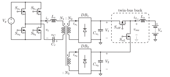
Fig shows the main circuit of the three-phase EPT with the separated DC-link topology presented . It is a three-stage input-series-output-parallel configuration with

3.The Proposed Overall Individual DC Voltage Balance Strategy.
When renewable energy sources and DC loads are connected with the DC ports of EPT (e.g., DC ports A_H and A_L, shown in Fig. 1) or component parameter mismatch occurs, there will be power unbalance among different PMs. If the power unbalance is beyond the adjustment capability of the DC voltage balance controller, DC voltages will be unbalanced. In this section, the renewable energy source and DC load scenario will be analyzed as an example.

4.Realization of the Proposed Overall Individual DC Voltage Balance Strategy.
The proposed strategy contains two parts: an individual high-voltage DC-link balance strategy in the isolation stage and an individual low-voltage DC-link balance strategy in the output stage.

5.Conclusions.
In this paper, an overall individual DC voltage balance strategy has been proposed for EPT with the separated DC-link topology in this paper. The DC voltage balance capabilities of the three overall individual DC voltage balance strategies have been analyzed and ranked. The ranking results indicate that the proposed strategy has the strongest DC voltage balance capability. This conclusion is supported by the experimental verification. The experimental results have shown that the individual high-voltage and low-voltage DC-links can be well balanced with the proposed strategy when there are severe component parameter mismatches or there is a large proportion of DC power in the total power. In fact, with the proposed strategy, the individual high-voltage and low-voltage DC-links can be balanced under severe unbalanced conditions as long as the powers flowing through the PM are within the maximum allowed power .
Source: IEEE Xplore.
Statement: Respect the original, good articles worth sharing, if there is infringement please contact delete.