I. Clarify the Concepts First: EHV and UHV
| Term |
English |
Voltage Range |
Typical Levels |
| Extra-High Voltage |
EHV |
330kV – 750kV |
330kV, 500kV, 750kV |
| Ultra-High Voltage |
UHV |
≥1000kV (AC) / ≥±800kV (DC) |
1000kV AC, ±800kV, ±1100kV DC |
| High Voltage |
HV |
110kV – 330kV |
110kV, 220kV |
In one sentence: EHV/UHV is the main corridor for "cross-province, cross-region, and cross-large-base" power transmission.
II. Why Use EHV/UHV Transmission?
1. The Physics: Higher Voltage, Lower Line Loss
Transmitted power P = √3 × U × I, while line loss:
Ploss = 3 × I² × R = P² × R / U²
Every doubling of voltage cuts line loss to 1/4 for the same power.
| Voltage Level |
Economic Distance |
Transfer Capacity |
Typical Loss |
| 220kV |
200–500km |
0.2–0.5 million kW |
Moderate |
| 500kV |
500–1000km |
1–2 million kW |
Lower |
| 1000kV AC |
1000–2000km |
5–10 million kW |
Very low |
| ±800kV DC |
1500–2500km |
8–10 million kW |
Lowest |
2. Spatial Mismatch Between Resources and Loads
China's energy layout is a classic "west-to-east power, north-to-south power" pattern:
- West/North: abundant hydro, wind, solar, and coal resources, but limited local consumption
- East/Coast: developed economies with dense electricity demand but scarce energy
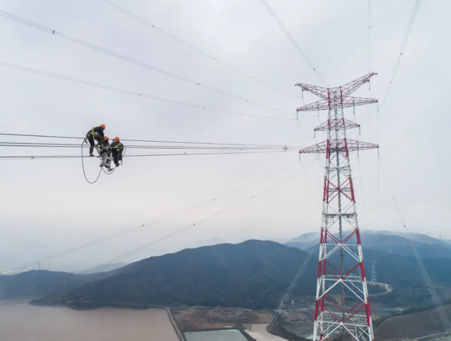
Without UHV, western power cannot reach the east — this is why UHV is vividly called the "power highway."
3. Economics: For Long Distances, Higher Voltage Pays Off
Total cost of long-distance transmission = line construction cost + line loss + station investment. As distance grows, the loss advantage of high voltage becomes increasingly significant — within the economic transmission distance, the higher the voltage level, the more cost-effective it is.
III. AC or DC? — Choosing Between Two Technical Routes
AC Transmission
DC Transmission (HVDC/UHVDC)
| Feature |
Description |
| Pros |
Lower line loss, larger capacity, no synchronization stability issues, converter stations can isolate faults |
| Cons |
High converter station cost, cannot tap power en route, requires filters |
Selection Rules
| Scenario |
Recommendation |
| Point-to-point over very long distance (>1000km) |
UHVDC (±800kV/±1100kV) |
| Regional grid interconnection, intermediate tapping |
EHV AC (500kV/1000kV) |
| Offshore wind transmission |
HVDC (±320kV etc.) |
| Large base to grid transmission |
UHVDC as the main choice |
China's practice: "DC for transmission, AC for networking" — cross-region point-to-point bulk transfer uses DC; in-region grids use AC.
IV. Conductor Selection: Why Do UHV Lines Use "Bundle Conductors"?
1. Corona Loss and Radio Interference
When the electric field on the conductor surface is too high, air is ionized producing corona discharge:
- Wastes energy (corona loss)
- Produces audible noise ("buzzing")
- Interferes with radio communications
2. The Principle of Bundle Conductors
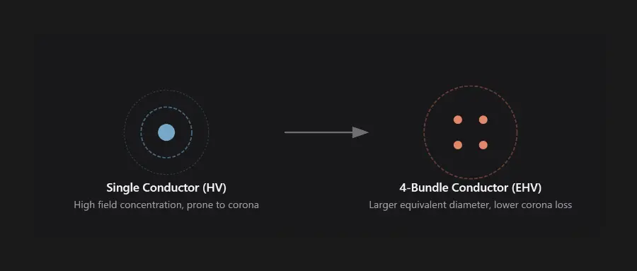
Split one large conductor into 2–8 sub-conductors, fixed at a certain spacing by spacers, forming a phase conductor:
      ○          ○      ○      ○
     ○ ○   or   ○ ○   ○ ○   ○ ○   (2-bundle, 4-bundle, 6-bundle, 8-bundle)
      ○          ○      ○      ○
Effect: The "equivalent radius" of the conductor increases, lowering surface electric field strength, thereby:
| Effect |
Description |
| Suppress corona |
Lower surface field, greatly reduced corona loss and noise |
| Increase current capacity |
More surface area for heat dissipation, higher transfer capacity |
| Reduce inductance |
Lower line reactance, higher transmission capability |
Typical bundle numbers:
- 500kV: 4-bundle
- 1000kV: 8-bundle
- ±800kV: 6-bundle (e.g., 6×625mm²)
3. Conductor Material and Cross-Section
- Material: mainly Steel-Cored Aluminum Conductor (ACSR); higher aluminum/steel ratio = better conductivity
- Large cross-section: UHV commonly uses 500–1250mm² large cross-section conductors to reduce resistance loss
- Trend: energy-efficient conductors (e.g., mid-strength aluminum-alloy core) to reduce line loss
V. Tower and Insulator Selection
1. Tower Types
| Type |
Feature |
Application |
| Suspension tower |
Suspends conductors, bears vertical loads |
Line main body |
| Tension tower |
Withstands conductor tension, high strength |
Corners, crossings, anchoring |
| Extra-large crossing tower |
Extra-high, long span |
Crossing rivers and straits |
2. Insulator Selection
EHV/UHV line insulators face the triple challenge of high voltage + long distance + pollution:
| Type |
Advantage |
Application |
| Porcelain insulator |
Mature, aging-resistant |
Traditional mainstream |
| Glass insulator |
Self-shattering makes zero-value faults easy to detect |
Maintenance-friendly |
| Composite insulator (silicone rubber) |
Strong hydrophobicity, anti-pollution-flashover, lightweight, maintenance-free |
UHV mainstream |
Key parameters:
- Creepage ratio: the more polluted the area, the longer the creepage distance required (Class IV pollution ≥ 31mm/kV)
- Lightning withstand: jumper and shield-wire configuration
- V-string / tension strings: V-shaped suspensions are common in UHV to prevent conductor galloping collisions
VI. Key Engineering Challenges for EHV/UHV Lines
| Challenge |
Solution |
| Corona and electromagnetic environment |
Bundle conductors, large cross-sections |
| High-altitude insulation |
More insulator discs, larger clearances |
| Conductor galloping |
Spacers, dampers, anti-galloping devices |
| Icing |
Mechanical strength designed for ice zones, de-icing devices |
| Lightning |
Full-length shield wires + low earth resistance |
| Pollution flashover |
Composite insulators, creepage ratio design |
VII. Core Logic Summary of EHV/UHV "Selection"
Step 1: Determine transfer capacity and distance
    ↓
Step 2: Choose DC or AC (distance >1000km and point-to-point → DC)
    ↓
Step 3: Determine voltage level (best economics for capacity & distance)
    ↓
Step 4: Conductor design (bundle number, cross-section, material → control corona & loss)
    ↓
Step 5: Insulation design (insulator type, disc count, creepage ratio → prevent pollution flashover)
    ↓
Step 6: Mechanical structure (towers, anti-galloping, anti-icing)
    ↓
Step 7: Supporting equipment (circuit breakers, arresters, CTs/VTs, substations)
VIII. ROCKWILL and EHV/UHV Supporting Equipment
Although line construction is a large-scale project led by grid companies, ROCKWILL provides a key link in the supporting equipment for EHV/UHV systems:

ROCKWILL Related Products
| Product |
Voltage Level |
Role in UHV Systems |
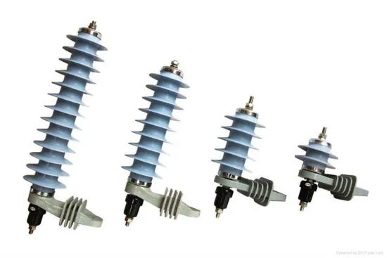
| Metal-oxide surge arrester |
0.22kV – 220kV |
Line and substation lightning protection |
| RHG Series GIS |
Up to 550kV |
High-voltage switching station equipment |
| SF6 circuit breaker |
Up to 245kV |
High-voltage line interruption protection |
| Power transformer |
110kV class |
High-voltage transformation |
| Hybrid GIS (HGIS) |
Up to 245kV |
Outdoor high-voltage layout |
Why Choose ROCKWILL for Supporting Equipment?
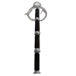
- Full-range surge arresters: 220kV-class arresters designed to IEC 60099-4, high nonlinearity ZnO varistors, low residual voltage, effective protection of line insulation
- KEMA certification: core products pass international authoritative type tests
- Outdoor weather-resistant design: validated in Class IV pollution, coastal salt spray, and -45°C extreme cold
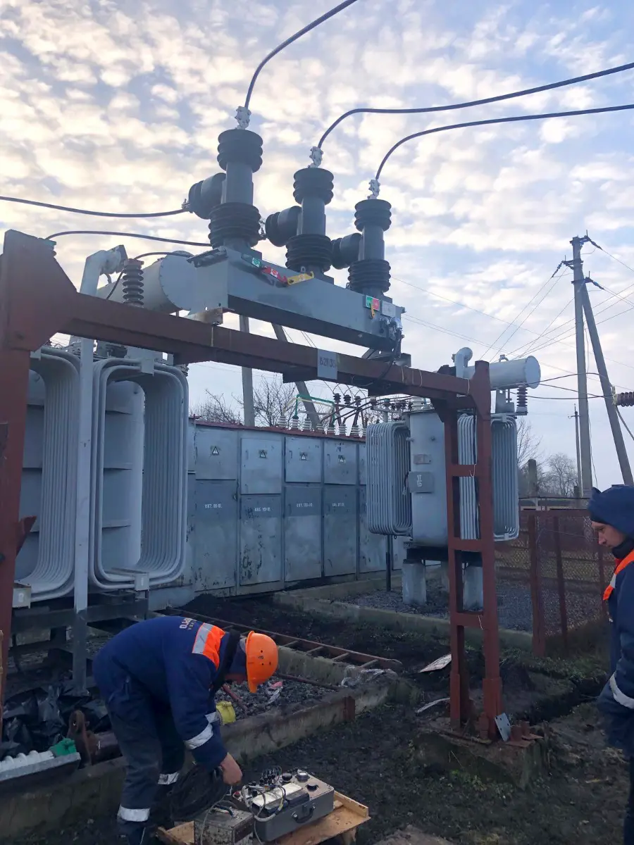
- Global supporting experience: from Southeast Asian distribution networks to Russian grid projects
The reliable operation of EHV/UHV lines depends on the reliability of every piece of supporting equipment. ROCKWILL provides a full range of high-voltage supporting products from arresters to switchgear, safeguarding the "power highway."
Contact us:
Edited From:Dyson

 Login
Login