Search


Rockwill Earthing Transformer: What It Is and How It Differs from a Standard Power Transformer

Rockwill earthing transformer: definition, purpose, and key differences from standard power transformers for neutral grounding applications.

Rockwill
Field: Manufacturing
10Year<
China
Add us on Google
 

What Is an Earthing (Grounding) Transformer?

An earthing transformer is a special protection-class device in power systems. Its core mission is to provide an artificial neutral point for delta-connected high-voltage distribution systems that either lack a neutral point or cannot have one brought out. The vast majority of earthing transformers use a Zigzag (Z-type) winding configuration. Through this special design, they create a zero-sequence current path and, together with an arc suppression coil or neutral grounding resistor cabinet, form a complete neutral earthing assembly that ensures the safe and stable operation of the power network.

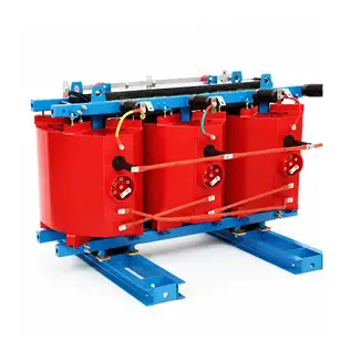
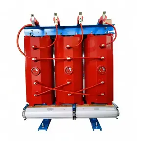
Neutral Grounding/earthing Transformer Dry Type Power Transformer direct supply 6kV 6.3kV 6.6kV 10kV 10.5kV 11kV

Dry Type Neutral Grounding/earthing Transformer

Core Functions

  • Artificial neutral point creation: In 10 kV and 35 kV distribution networks, the low-voltage side of the main transformer is typically delta-connected, leaving the system without an accessible neutral point. When connected to the busbar, the earthing transformer's special three-phase winding configuration converges into a common neutral point, providing a physical interface for connecting earthing equipment.
  • Zero-sequence fault current conduction: When a single-phase-to-earth fault occurs, voltage imbalance across the three phases generates zero-sequence current. The Z-type winding provides a low-impedance path for this zero-sequence current, enabling the protection relay to quickly identify and clear the fault. It also effectively suppresses arcing ground overvoltage, preventing insulation breakdown in cables and equipment.
  • Dual-purpose station service function: Some earthing transformers are fitted with an additional low-voltage secondary winding (e.g., ZNyn connection), supplying power to station lighting, control supplies, and other low-voltage loads while also providing the artificial neutral point. This type, known as an "earthing and station service transformer," can reduce overall project investment.

Essential Differences Between Earthing Transformers and Standard Power Transformers

Earthing transformers and standard distribution/power transformers differ fundamentally in their underlying design logic. The differences are manifested in six key dimensions:

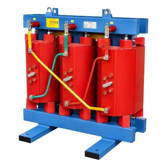
Customizable Amorphous Alloy Dry-type Transformers-10kV 35kV

Standard Dry-type Transformer

1. Winding Configuration and Magnetic Circuit Response (Most Critical Difference)

  • Earthing transformer (Zigzag Z-type winding): Each core limb carries two winding segments belonging to different phases, wound in opposite directions and connected in reverse series. Under normal balanced three-phase operation, positive-sequence and negative-sequence fluxes cancel each other out, resulting in virtually no excitation loss in the core. When a single-phase-to-earth fault occurs, zero-sequence fluxes from different phases are in the same direction on the same core limb and reinforce each other, producing a controlled low zero-sequence impedance specifically designed to conduct earth fault current.
  • Standard power transformer (Yyn/Dyn conventional winding): Each core limb carries only the complete winding of its own phase. The design is intended to transmit positive-sequence and negative-sequence load power. Such transformers present a very high impedance to zero-sequence current; zero-sequence flux can only flow along leakage paths. Forcing such a transformer to serve as an earthed neutral point would cause severe heating and potentially equipment damage.

2. Design Objective and Evaluation Criteria

  • Earthing transformer: Design priority is zero-sequence impedance requirements and the ability to withstand short-duration earth faults. Its rating is not calculated on continuous load kVA but determined by the system's capacitive earth current and short-time thermal withstand requirements, typically rated on a 10 s or 30 s short-time duty basis. For the same rating, its physical size is often larger than that of a standard transformer. The core specification is "short-time capability to carry large single-phase earth fault current"; long-term normal load-carrying capacity is not the primary concern.
  • Standard power transformer: The core objective is the continuous and efficient transmission of three-phase active and reactive load. Design focuses on load loss, temperature rise limits, and long-term load-carrying capacity, with no consideration given to sustained zero-sequence fault current operation.

3. Operating Condition and Load Characteristics

  • Earthing transformer: The operating pattern can be described as "long-term no-load, short-term overload." During normal grid operation, it spends the vast majority of time in a no-load state with only minimal excitation current and very low losses. Only during the brief period of an earth fault does it carry significant zero-sequence fault current.
  • Standard power transformer: Operates under load year-round, continuously transmitting electrical energy. Load loss is the key indicator of its daily operating energy consumption.

4. Dual Impedance Characteristics

  • Earthing transformer: Exhibits a dual impedance nature — "very high positive-sequence impedance, very low zero-sequence impedance." During normal operation, the high impedance means it consumes almost no power; during a fault, the low impedance provides a clear path for zero-sequence current.
  • Standard power transformer: Zero-sequence impedance is very high, making zero-sequence current passage virtually impossible. Forcing an earthed neutral point through such a transformer to carry zero-sequence current can easily induce ferroresonance overvoltage, endangering network equipment.

5. Functional Role and System Position

  • Earthing transformer: A system-level protection device whose primary role is overvoltage protection and earth fault protection support. It does not perform routine power transmission or distribution functions.
  • Standard power transformer: An energy transmission device and the core hub for voltage transformation (step-up, step-down) and power distribution within the network.

6. Associated Equipment Requirements

  • Earthing transformer: Its neutral point must be used together with dedicated current-limiting or compensation equipment, such as a low-resistance grounding cabinet, arc suppression coil, or earthing reactor, to form a complete earth protection system.
  • Standard power transformer: Its neutral point is typically earthed simply according to system requirements (e.g., solidly earthed or unearthed), without the need for additional complex current-limiting or arc-suppression equipment.

Summary of the Fundamental Distinction

A standard power transformer is an energy transmission device whose purpose is to "transmit three-phase load power." Its winding configuration prevents it from conducting zero-sequence current. In contrast, the earthing Z-type transformer is a protection-class device whose sole core purpose is to "create an artificial neutral point and conduct zero-sequence earth fault current." It exchanges very low normal no-load losses for the safety and reliability of the power network under single-phase-to-earth fault conditions.

Edited From:Echo

Give a tip and encourage the author!

Comments

Share your question or perspective
WhatsApp
Send inquiry
+86
Click to upload file
Download
Get the IEE Business Application
Use the IEE-Business app to find equipment, obtain solutions, connect with experts, and participate in industry collaboration anytime, anywhere—fully supporting the development of your power projects and business.
Login
or continue with
New here?
Register