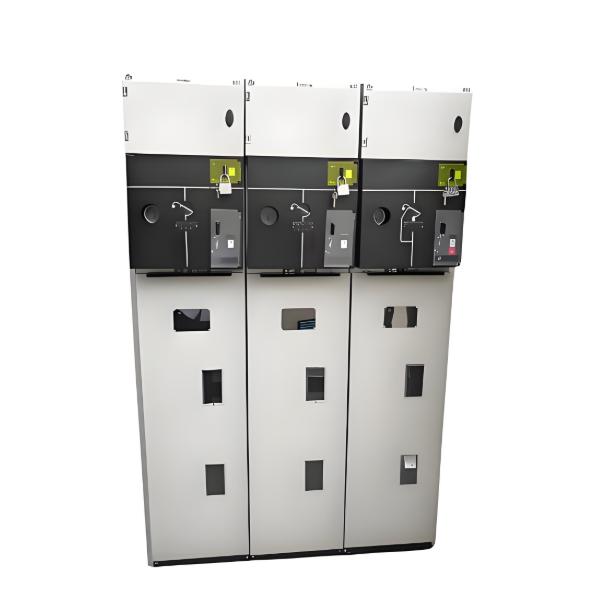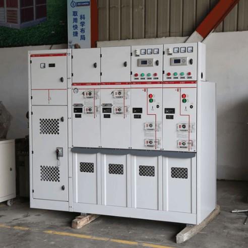
Patent Title: Ring Main Unit Udstyret med en Luftcirkulationstruktur
Application Publication No.: CN 106099739 A
Application Publication Date: 2016.11.09
Application Number: 201610680193.9
Application Date: 2016.08.16
Patent Agency: Tianjin Sanli Patent & Trademark Agency Ltd. 12107
International Patent Classification (Int.Cl.):
• H02B 13/00 (2006.01)
• H02B 1/56 (2006.01)
Abstract:
Opfindelsen offentliggør en ring main unit udstyret med en luftcirkulationstruktur. Bunden af kabinetet for ring main unit er af en kompositstruktur, der består af et opvarmningslag. Opvarmningslaget er udstyret med opvarmningsstave, en fuktighedssensor og en blæser. Topvæggen af opvarmningslaget er udstyret med gennemtrængningshuller/permeable hul. Blæseren er placeret på en side af opvarmningslaget, og opvarmningsstaverne er jævnt fordelt inden i opvarmningslaget. Toppen af kabinetet for ring main unit er udstyret med en åbning, hvor en trykforhøjende dækplade er installeret. Midten af trykforhøjende dækpladen er udstyret med en ventilationsmekanisme, der inkluderer lameller og en filterplade arrangeret fra top til bund. Temperatursensoren, opvarmningsstaverne og blæseren er alle forbundet til en styreenhed. Når fugtigheden er høj og overstiger en forudindstillet tærskel, kontrollerer styreenheden at opvarmningsstaverne opvarmes og at blæseren blæser luft. Den varme luft bliver ledt opad gennem gennemtrængningshullerne/permeable hul og udspidset gennem trykforhøjende dækpladen, hvilket resulterer i tørring.
Claims:
En ring main unit udstyret med en luftcirkulationstruktur, karakteriseret ved, at bunden af kabinetet for ring main unit er af en kompositstruktur, der omfatter et opvarmningslag; opvarmningslaget er udstyret med opvarmningsstave, en fuktighedssensor og en blæser; topvæggen af opvarmningslaget er udstyret med gennemtrængningshuller/ permeable hul; blæseren er placeret på en side af opvarmningslaget; opvarmningsstaverne er jævnt fordelt inden i opvarmningslaget; toppen af kabinetet for ring main unit er udstyret med en åbning, hvor en trykforhøjende dækplade er installeret; midten af trykforhøjende dækpladen er udstyret med en ventilationsmekanisme; ventilationsmekanismen inkluderer lameller og en filterplade arrangeret fra top til bund; temperatursensoren, opvarmningsstaverne og blæseren er alle forbundet til en styreenhed.
Ring main unit udstyret med en luftcirkulationstruktur ifølge krav 1, karakteriseret ved, at en fast akse er svaret ved åbningen; den faste akse er skubbekoblet til det første enden af trykforhøjende dækpladen; trykforhøjende dækpladen er udstyret med ventilationshuller; det andet ende af trykforhøjende dækpladen er skubbekoblet til en kolbenstang; en cylinder er fast forbindelse til switchgear kabinet shell via en cylinder fastholdelsesbræt; switchgear kabinet shell er også udstyret med en tryksensor og en lydalarm; tryksensoren, lydalarmen og cylindren er alle forbundet til styreenheden.
Description:
Teknisk Felt [0001]
Denne opfindelse relaterer sig til tekniske feltet for elektrisk udstyr, og specielt til en ring main unit udstyret med en luftcirkulationstruktur.
Baggrundskunst [0002]
En Ring Main Unit (RMU) er et sæt af strømtransmissions- og -fordelings elektrisk udstyr (højspændingskontaktorer) installeret indeni et metal eller ikke-metal isoleret kabinet eller samlet som et modulært ringnet-strømforsyningsenhed. Dens kerne bruger lastskalder og sikringer, og har fordele som enkel struktur, lille størrelse, lav kostpris, forbedrede strømforsyningsparametre og -ydeevne, samt forbedret strømforsynings Sikkerhed. Det anvendes bredt i strømforsyningsstationer og boksformede understations ved belastningscentre som bybebyggelser, høje bygninger, store offentlige bygninger og industrielle virksomheder.
[0003] I de senere år har lukkede ring main units været vidt anvendte i understationer, skiftstationer og brugers fordelingskabinetter. De fleste af disse ring main units er installeret på stueetagen eller i kælderlokaler, hvor ventilationsforholdene er dårlige, og miljøfugtigheden varierer betydeligt. Dette kan let føre til fugtindtrængen i udstyret indeni de lukkede ring main units. Langvarig drift under sådanne forhold kan gradvis reducere isolationen af udstyret indeni ring main unit, hvilket kan føre til hændelser som udstyr isolation nedbrydning og udstyr eksplosion, alvorligt truer strømnettet og personlig sikkerhed. Derfor er det nødvendigt at designe en enhed, der kan opnå ventilation og tørring af udstyret indeni ring main unit i koordinering med eksisterende kontrolsoftware.
Oversigt over Opfindelsen [0004]
Formålet med denne opfindelse er at levere en ring main unit udstyret med en luftcirkulationstruktur, med henblik på at løse de tekniske problemer, der findes i den tidligere kunst.
[0005] For at opnå formålet med denne opfindelse er den tekniske løsning, som denne opfindelse anvender, følgende:
[0006] En ring main unit udstyret med en luftcirkulationstruktur, hvor bunden af kabinetet for ring main unit er af en kompositstruktur, der omfatter et opvarmningslag. Opvarmningslaget er udstyret med opvarmningsstave, en fuktighedssensor og en blæser. Topvæggen af opvarmningslaget er udstyret med gennemtrængningshuller/permeable hul. Blæseren er placeret på en side af opvarmningslaget. Opvarmningsstaverne er jævnt fordelt inden i opvarmningslaget. Toppen af kabinetet for ring main unit er udstyret med en åbning, hvor en trykforhøjende dækplade er installeret. Midten af trykforhøjende dækpladen er udstyret med en ventilationsmekanisme. Ventilationsmekanismen inkluderer lameller og en filterplade arrangeret fra top til bund. Temperatursensoren, opvarmningsstaverne og blæseren er alle forbundet til en styreenhed.
[0007] Desuden er en fast akse svaret ved åbningen. Den faste akse er skubbekoblet til det første enden af trykforhøjende dækpladen. Trykforhøjende dækpladen er udstyret med ventilationshuller. Det andet ende af trykforhøjende dækpladen er skubbekoblet til en kolbenstang. En cylinder er fast forbindelse til switchgear kabinet shell via en cylinder fastholdelsesbræt. Switchgear kabinet shell er også udstyret med en tryksensor og en lydalarm. Tryksensoren, lydalarmen og cylindren er alle forbundet til styreenheden.
[0008] I forhold til den tidligere kunst har denne opfindelse følgende fordele: når fuktholdigheden er høj og overstiger en forudindstillet tærskel, kontrollerer styreenheden, at opvarmningsstaverne opvarmes og at blæseren blæser luft. Den varme luft bliver ledt opad gennem gennemtrængningshullerne/permeable hul og udspidset gennem trykforhøjende dækpladen, hvilket resulterer i tørring.
[0009]
En udførelse af ring main unit ifølge denne opfindelse.
Trykforhøjende dækpladen leveret af denne opfindelse.
Nøjagtig Beskrivelse [0012]
Følgende beskriver denne opfindelse yderligere med henvisning til de vedhæftede tegninger og specifikke udførelser. Det skal forstås, at de specifikke udførelser, der er beskrevet her, er kun ment som eksempler på denne opfindelse og ikke som begrænsende for denne opfindelse.
[0013] Det skal bemærkes, at termen "forbundet" og ord, der bruges til at udtrykke "forbindelse", som "forbundet til" og "koplet", som anvendes i denne ansøgning, kan betyde, at en komponent er direkte forbundet til en anden komponent, eller at en komponent er forbundet til en anden komponent gennem andre komponenter.
[0014] Som vist på figurer 1 og 2, en ring main unit udstyret med en luftcirkulationstruktur. Bunden af kabinetet for ring main unit er af en kompositstruktur, der omfatter et opvarmningslag. Opvarmningslaget er udstyret med opvarmningsstave, en fuktighedssensor og en blæser. Topvæggen af opvarmningslaget er udstyret med gennemtrængningshuller/permeable hul. Blæseren er placeret på en side af opvarmningslaget. Opvarmningsstaverne er jævnt fordelt inden i opvarmningslaget. Toppen af kabinetet for ring main unit er udstyret med en åbning, hvor en trykforhøjende dækplade er installeret. Midten af trykforhøjende dækpladen er udstyret med en ventilationsmekanisme. Ventilationsmekanismen inkluderer lameller og en filterplade arrangeret fra top til bund. Temperatursensoren, opvarmningsstaverne og blæseren er alle forbundet til en styreenhed.
[0015] Det skal bemærkes, at styreenheden kan være en enkeltchip mikrocomputer (microcontroller).
[0016] Desuden er en fast akse svaret ved åbningen. Den faste akse er skubbekoblet til det første enden af trykforhøjende dækpladen. Trykforhøjende dækpladen er udstyret med ventilationshuller. Det andet ende af trykforhøjende dækpladen er skubbekoblet til en kolbenstang. En cylinder er fast forbindelse til switchgear kabinet shell via en cylinder fastholdelsesbræt. Switchgear kabinet shell er også udstyret med en tryksensor og en lydalarm. Tryksensoren, lydalarmen og cylindren er alle forbundet til styreenheden.
[0017] I forhold til den tidligere kunst har denne opfindelse følgende fordele: når fuktholdigheden er høj og overstiger en forudindstillet tærskel, kontrollerer styreenheden, at opvarmningsstaverne opvarmes og at blæseren blæser luft. Den varme luft bliver ledt opad gennem gennemtrængningshullerne/permeable hul og udspidset gennem trykforhøjende dækpladen, hvilket resulterer i tørring.
[0018] Ovenstående beskrivelser er blot foretrukne udførelser af denne opfindelse. Det skal bemærkes, at for dem, der har almindelig fagkendskab, kan flere forbedringer og ændringer foretages uden at forlade principperne for denne opfindelse. Disse forbedringer og ændringer bør også betragtes som falder inden for beskyttelsesområdet for denne opfindelse.


