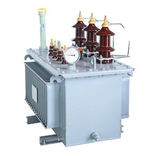
1.Rectifier Transformer: Principle and Overview
A rectifier transformer is a specialized transformer designed to supply rectifier systems. Its working principle is the same as that of a conventional transformer — it operates based on electromagnetic induction and is used to transform alternating voltage. A typical transformer has two electrically isolated windings — primary and secondary — wound around a common iron core.
When the primary winding is connected to an AC power source, alternating current flows through it, generating a magnetomotive force (MMF), which produces an alternating magnetic flux in the closed iron core. This changing flux cuts across both the primary and secondary windings, inducing an alternating voltage of the same frequency in the secondary winding.
The ratio of the number of turns between the primary and secondary windings equals the voltage ratio. For example, if a transformer has 440 turns on the primary and 220 turns on the secondary, with 220V input on the primary side, the output voltage on the secondary will be 110V. Some transformers may have multiple secondary windings or taps, allowing several different output voltages to be obtained.
2.Characteristics of Rectifier Transformers
Rectifier transformers work together with rectifiers to form rectification equipment, enabling conversion of AC power into DC power. Such rectifier systems are the most commonly used DC power sources in modern industrial enterprises, widely applied in HVDC transmission, electric traction, rolling mills, electroplating, electrolysis, and other fields.

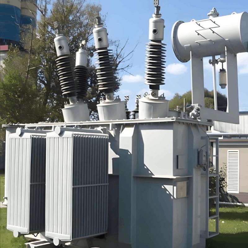
The primary (also called network side) of a rectifier transformer connects to the AC power grid, while the secondary (also called valve side) connects to the rectifier. Although its basic structure and operating principle are similar to those of a conventional transformer, the load — a rectifier — differs significantly from normal loads, leading to unique design and operational characteristics:
2.2 Non-Sinusoidal Current Waveforms
In a rectifier circuit, each arm conducts only during a portion of the cycle, resulting in non-sinusoidal current waveforms — typically close to discontinuous rectangular pulses. Consequently, both primary and secondary winding currents are non-sinusoidal.
For example, in a three-phase bridge rectifier with Y/Y connection, the current waveform shows distinct pulse patterns. When thyristors are used for rectification, the larger the firing delay angle, the steeper the current rise/fall, increasing harmonic content. This leads to higher eddy current losses. Since the secondary winding conducts current only part of the time, the utilization rate of the rectifier transformer is lower than that of a conventional transformer. Therefore, for the same power rating, rectifier transformers tend to be larger and heavier.
2.3 Equivalent (Average) Apparent Power Rating
In a conventional transformer, the input and output power are equal (ignoring losses), so the rated capacity is simply the apparent power of either winding. However, in a rectifier transformer, the primary and secondary currents may differ in waveform (e.g., in half-wave rectification), making their apparent powers unequal.
Therefore, the transformer's capacity is defined as the average of the primary and secondary apparent powers, known as the equivalent capacity:

where S1 is the primary apparent power and S2 is the secondary apparent power.
2.4 High Short-Circuit Withstand Capability
Rectifier transformers must have high mechanical strength to withstand short-circuit electromagnetic forces due to frequent faults or sudden load changes (e.g., motor starting). Ensuring dynamic stability under short-circuit conditions is a critical consideration in design and manufacturing.
3.Main Applications of Rectifier Transformers
Rectifier transformers serve as the power source for rectifier equipment. Their main feature is converting AC input on the primary side into DC output via rectifying elements on the secondary side. "Power conversion" includes rectification, inversion, and frequency conversion, among which rectification is the most widely used. Transformers used to supply rectifier devices are called rectifier transformers. Most industrial DC power supplies are obtained by combining AC grids with rectifier transformers and rectifier circuits.
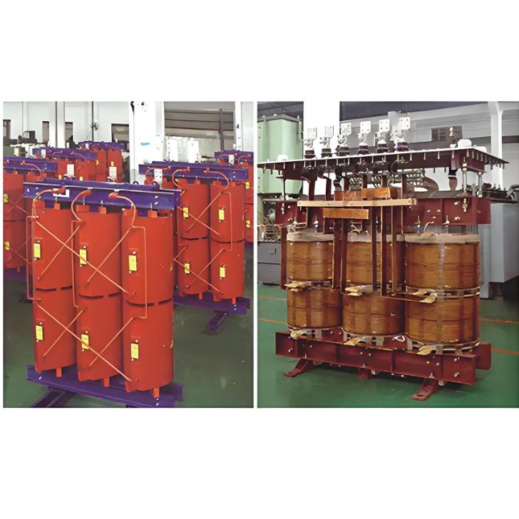
3.1 Electrochemical Industry
This is the largest application area for rectifier transformers:
Electrolysis of metal compounds to produce aluminum, magnesium, copper, and other non-ferrous metals
Chlor-alkali production via saltwater electrolysis
Hydrogen and oxygen generation through water electrolysis
These processes require high-current, low-voltage DC power, similar in some aspects to electric arc furnace transformers. As such, rectifier transformers share structural features with furnace transformers.
The most distinctive feature of rectifier transformers is that the secondary current is no longer sinusoidal AC. Due to the unidirectional conduction of rectifying elements, phase currents become pulsating and unidirectional. After filtering, this pulsating current becomes smooth DC.
The secondary voltage and current depend not only on transformer capacity and connection group but also on the rectifier circuit configuration (e.g., three-phase bridge, dual anti-parallel with balancing reactor). Even for the same DC output, different rectifier circuits require different secondary voltages and currents. Thus, parameter calculation for rectifier transformers starts from the secondary side and is based on the specific rectifier topology.
Because rectifier winding currents contain rich high-order harmonics, they pollute the AC grid and reduce power factor. To mitigate harmonics and improve power factor, the pulse number of the rectifier system must be increased, typically achieved through phase-shifting techniques. The purpose of phase shifting is to introduce a phase displacement between line voltages at homologous terminals of the secondary windings.
3.2 Traction DC Power Supply
Used in mining or urban electric locomotives with DC overhead lines.
Frequent short-circuit faults due to overhead line exposure
Large fluctuations in DC load
Frequent motor starting causes short-term overloads
To handle these conditions:
Lower temperature rise limits
Reduced current density
Impedance is about 30% higher than standard power transformers
3.3 Industrial Drive DC Power Supply
Primarily used to supply DC motors in electric drive systems, such as:
Armature and field excitation for rolling mill motors
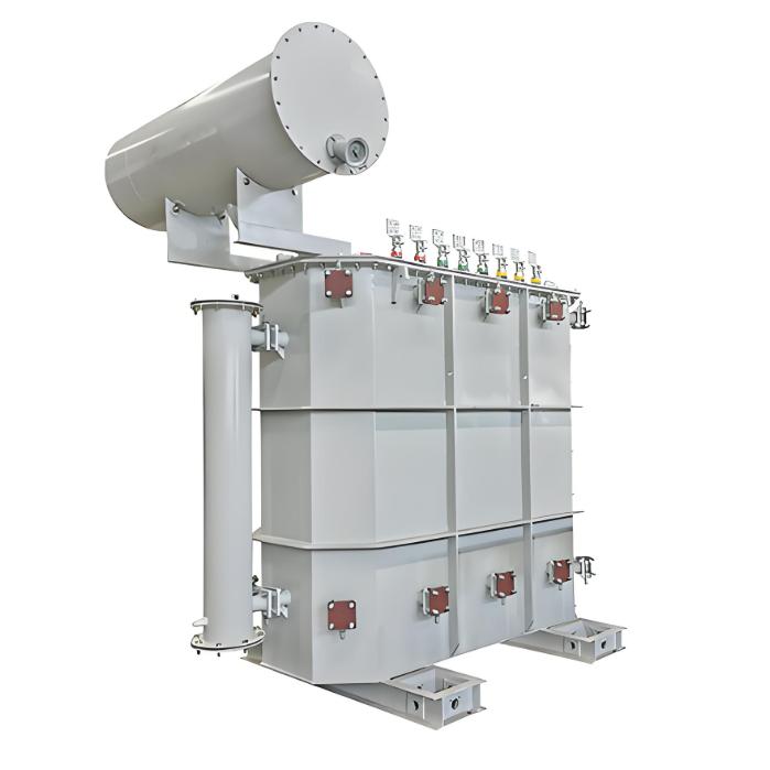
3.4 High-Voltage Direct Current (HVDC) Transmission
Operating voltages typically above 110 kV
Capacities range from tens of thousands to hundreds of thousands of kVA
Special attention required for combined AC and DC insulation stress to ground
Other Applications:
DC power for electroplating or electro-machining
Excitation power supplies for generators
Battery charging systems
Electrostatic precipitator (ESP) power supplies